Non-contact ic system and mobile terminal
a non-contact ic and mobile terminal technology, applied in the direction of instruments, liquid/fluent solid measurement, display means, etc., can solve the problems of increasing the power consumption of such batteries, and affecting the stability of non-contact ic cards
- Summary
- Abstract
- Description
- Claims
- Application Information
AI Technical Summary
Benefits of technology
Problems solved by technology
Method used
Image

Examples
first embodiment
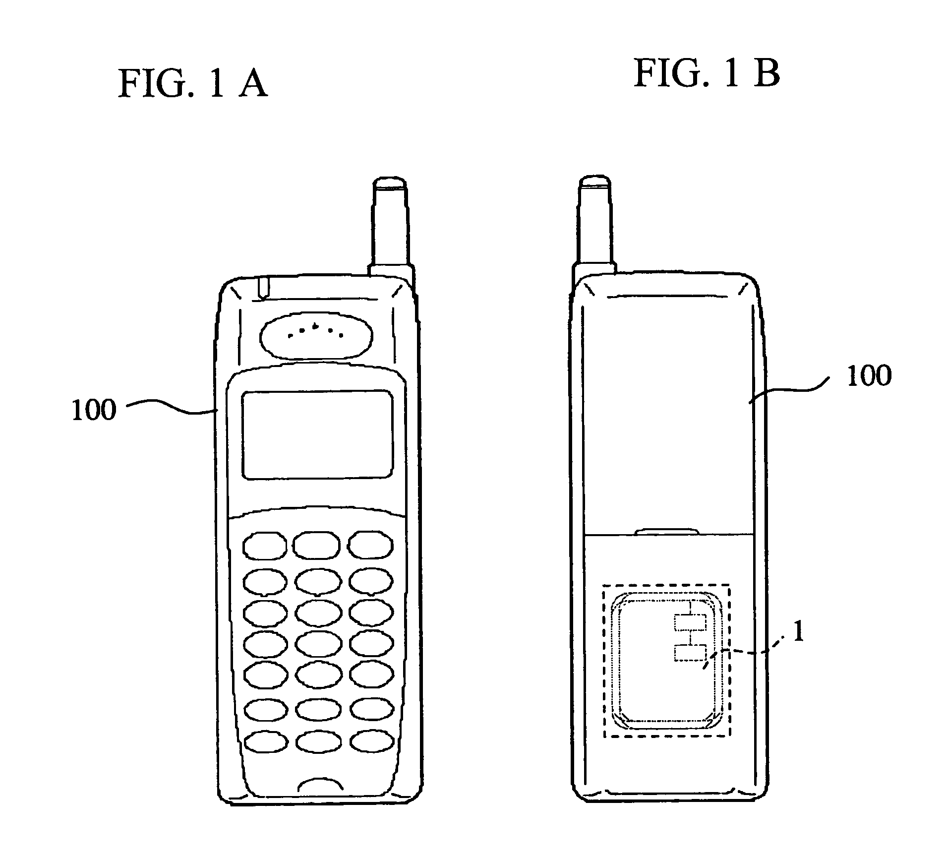
[0021]FIG. 1A is a front view of a mobile terminal employing a non-contact IC system according to a first embodiment of the invention, and FIG. 1B shows its rear view. This is an example in which the invention is applied to a communication terminal such as a mobile telephone in which a non-contact IC module is mounted.
[0022] In FIGS. 1A and 1B, numeral 100 designates a mobile telephone (mobile terminal), and numeral 1 designates the non-contact IC system housed in the mobile telephone 100.
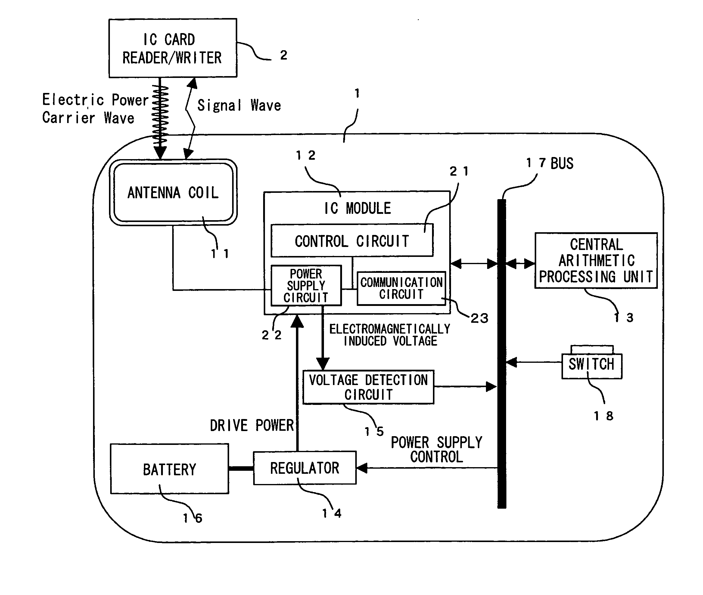
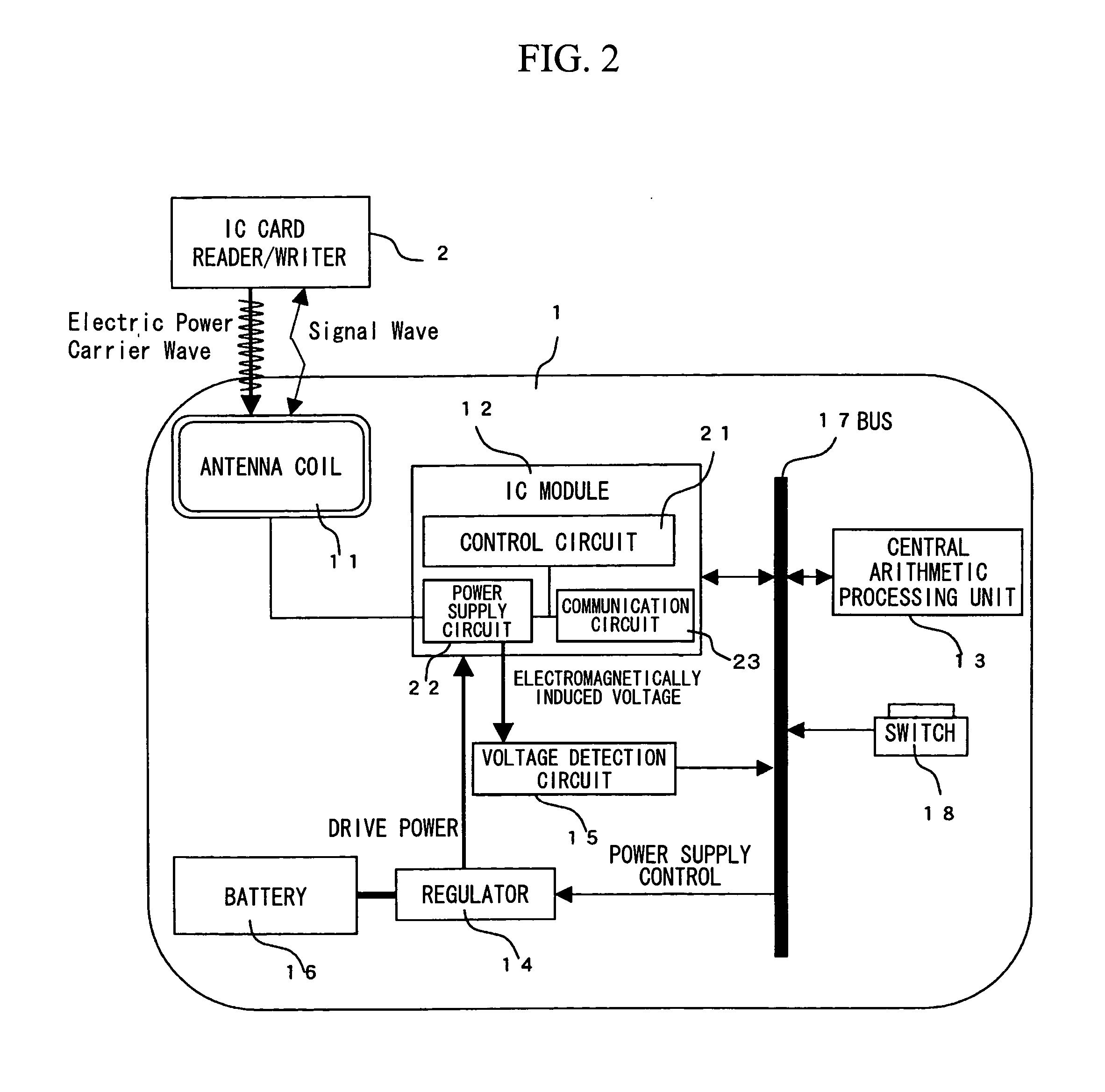
[0023] Conventional non-contact IC cards do not have an external power source such as a secondary cell or a battery but utilize electric power by electromagnetic induction via the antenna coil as drive power to the IC module. In contrast, the non-contact IC system 1 of the invention utilizes electric power supplied from the battery of the mobile telephone 100 as drive power, and the electric power by electromagnetic induction is primarily utilized for making a decision in controlling the power su...
second embodiment
[0044]FIG. 4 shows a control sequence diagram of a power supply control operation in the non-contact IC system according to a second embodiment of the invention. The steps that are carried out for the same control sequence as in FIG. 3 are indicated with the same reference numbers, and the explanations of the overlapping portions are omitted. The hardware structure of the non-contact IC system of the embodiment is the same as that shown in FIG. 2.
[0045] In the first embodiment, the detection of voltage change in the voltage detection circuit 15 was described as a trigger for carrying out step 201. Instead, in the second embodiment, as shown in FIG. 4, a change in the state of the switch 18 is detected as such a trigger.
[0046] Namely, the central arithmetic processing unit 13 monitors a change in the switch 18. Upon detection of a change, the central arithmetic processing unit 13 starts the timer in preparation for the providing of electric power to the IC module 12 at step 201. Th...
PUM
 Abstract
Description
Claims
Application Information
 - R&D
- Intellectual Property
- Life Sciences
- Materials
- Tech Scout
- Unparalleled Data Quality
- Higher Quality Content
- 60% Fewer Hallucinations
Browse by: Latest US Patents, China's latest patents, Technical Efficacy Thesaurus, Application Domain, Technology Topic, Popular Technical Reports.
© 2025 PatSnap. All rights reserved.Legal|Privacy policy|Modern Slavery Act Transparency Statement|Sitemap|About US| Contact US: help@patsnap.com