
Method and system for calibrating multiple types of base stations in a wireless network

a wireless network and wireless network technology, applied in the field of wireless communication, can solve the problems of conventional methods and systems for obtaining calibration data, degraded performance of antenna array systems, and high cost of antenna arrays

Inactive Publication Date: 2007-03-08
SAMSUNG ELECTRONICS CO LTD
View PDF2 Cites 32 Cited by
  • Summary
  • Abstract
  • Description
  • Claims
  • Application Information

AI Technical Summary

Problems solved by technology

Therefore, antenna arrays used in association with former signal processors had to achieve high quality standards to perform acceptably, making antenna arrays expensive.
Additionally, these antenna array systems experienced degraded performance when temperatures changed, humidity levels changed, or other environmental conditions changed because the characteristics of the antenna array diverged from the expected ideal characteristics under these altered environmental conditions.
Conventional methods and systems for obtaining the calibration data, however, have many drawbacks.
The known calibration systems may include extensive measuring equipment that is both unwieldy and expensive.
Some conventional calibration methods are sensitive to drifts in system parameters, and these drifts lead to inaccuracies in the calibration data obtained using these methods.
Because conventional calibration methods may be sufficiently time-consuming that periodic recalibration is impractical, some antenna arrays are calibrated only in the factory or upon initial installation, and thereafter their characteristics may diverge from the factory calibration data as the antenna array ages or as environmental conditions change.
Antenna arrays that have not been individually and recently calibrated in their current environment may have inaccuracies in their array calibration data that may result in performance degradation.
Current calibration systems, however, are typically designed for specific vendors and systems, are manufactured in low volume, and are relatively expensive.

Method used


Image

  • Method and system for calibrating multiple types of base stations in a wireless network
  • Method and system for calibrating multiple types of base stations in a wireless network
  • Method and system for calibrating multiple types of base stations in a wireless network

Examples


Embodiment Construction

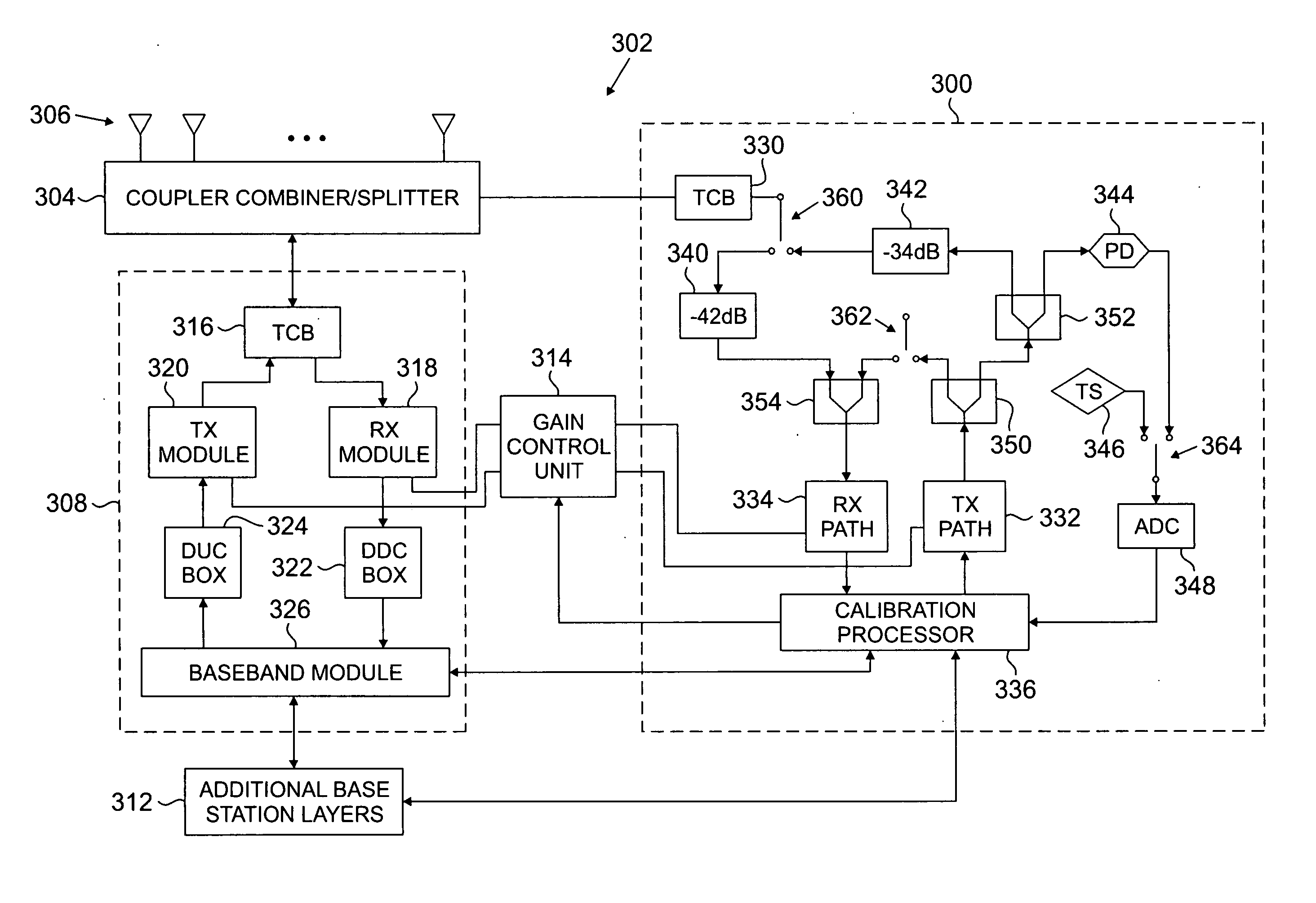
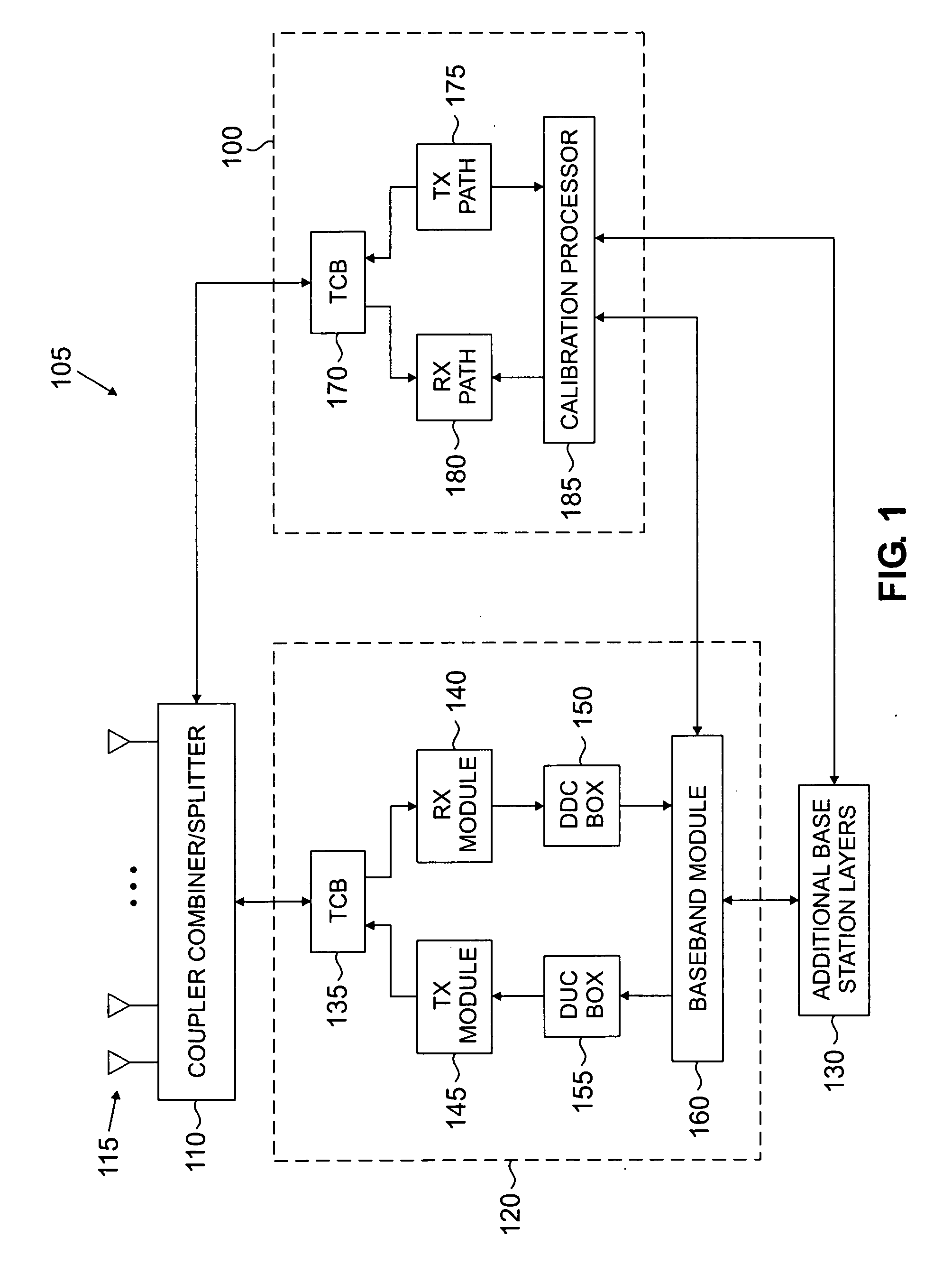
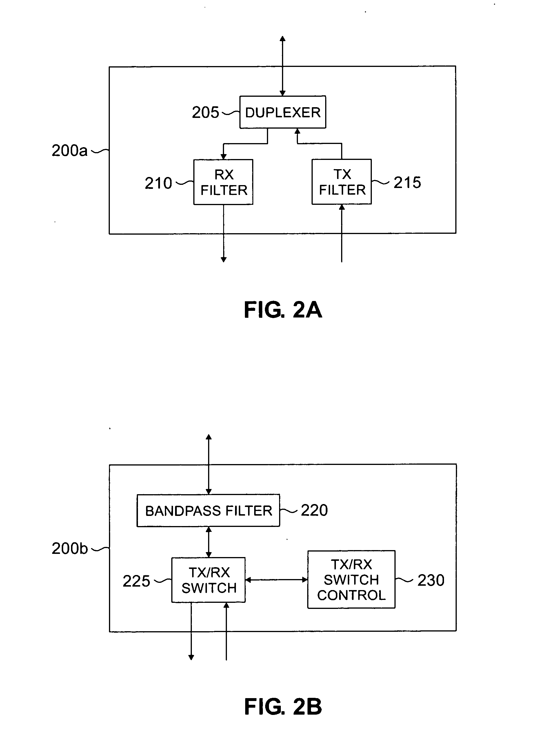
[0021]FIGS. 1 through 4, discussed below, and the various embodiments used to describe the principles of the present disclosure in this patent document are by way of illustration only and should not be construed in any way to limit the scope of the disclosure. Those skilled in the art will understand that the principles of the present disclosure may be implemented in any suitably arranged wireless network.

[0022]FIG. 1 illustrates a calibration system 100 for an adaptive antenna base station 105 according to one embodiment of the present disclosure. In addition to calibration system 100, base station 105 comprises a coupler combiner / splitter 110, an adaptive antenna array 115, a plurality of antenna paths 120, and additional base station layers 130. A single antenna path 120 is illustrated for simplicity. However, it will be understood that each antenna of antenna array 115 is associated with a corresponding antenna path 120. In addition, it will be understood that base station 105 ...


PUM


Abstract

A method of calibrating multiple types of base stations is provided. The method includes selecting one of a plurality of technology types for the wireless base station. The wireless base station has an adaptive antenna array. A calibration is performed for the wireless base station based on the selected technology type.

Description

CROSS-REFERENCE TO RELATED APPLICATION AND CLAIM OF PRIORITY [0001] The present disclosure is related to that disclosed in U.S. Patent Application Serial No. [2004.10.003.WS0], filed concurrently herewith, entitled “CALIBRATION SYSTEM ARCHITECTURE FOR CALIBRATING MULTIPLE TYPES OF BASE STATIONS IN A WIRELESS NETWORK.” U.S. Patent Application Serial No. [2004.10.003.WS0] is assigned to the assignee of the present application. The subject matter disclosed in U.S. Patent Application Serial No. [2004.10.003.WS0] is hereby incorporated by reference into the present disclosure as if fully set forth herein. TECHNICAL FIELD OF THE INVENTION [0002] The present disclosure relates generally to wireless communications and, more specifically, to a method and system for calibrating multiple types of base stations in a wireless network. BACKGROUND OF THE INVENTION [0003] In a base station of a wireless communication network, the antenna is the port through which radio frequency (RF) energy is coup...

Claims


Application Information

Patent Timeline
IPC IPC(8): H04B1/38
CPCH04W88/085H04B17/29H04B17/21
Inventor DING, YINONGRENSBURG, CORNELIUS VANTRIVEDI, AKSHAYA A.
Owner SAMSUNG ELECTRONICS CO LTD
Learn More