
Image processing apparatus, image processing method, image processing program, and recording medium

a technology of image processing and image processing method, applied in the field of image processing apparatus, image processing method, image processing program, and recording medium, can solve the problems of limited application range, failure to perform optimal eye estimation, and limitation of eye estimation

Inactive Publication Date: 2007-03-08
TOYOTA JIDOSHA KK
View PDF1 Cites 30 Cited by
  • Summary
  • Abstract
  • Description
  • Claims
  • Application Information

AI Technical Summary

Benefits of technology

[0015] According to the present invention described above, the state variables include the parameters for calculation of the model coordinates of the predetermined feature point, which are separated into the first parameter independent of the local motion and the second parameter dependent on the local motion. Therefore, the first parameter to converge at a specific value is separated from the second parameter varying with the local motion, whereby the model coordinates can be estimated accurately. The coordinates of the predetermined feature point after the overall motion of the 3D object are estimated from the model coordinates, using the third parameter for calculation of the overall motion of the 3D object. Therefore, the coordinates after the motion can be calculated, while dealing with the overall motion of the 3D object. Furthermore, the predicted values of the state variables are filtered using the estimates of the observation vector calculated from the estimated coordinates of the predetermined feature point and using the observation vector actually measured, whereby the parameters for estimation of the motion of the predetermined feature point can be directly filtered, so that the estimates of the state variables including these parameters can be accurately estimated. Therefore, the present invention permits accurate calculation of the output value about the motion of the predetermined feature point on the basis of the second parameter.
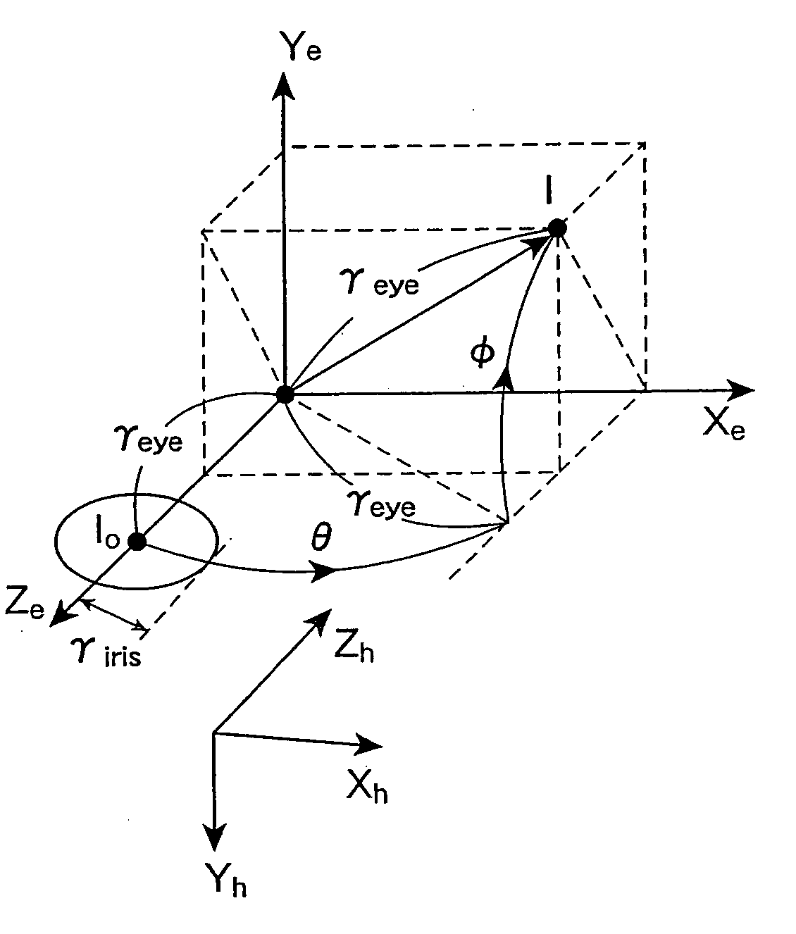
[0021] In this image processing apparatus, for the motion picture of the face taken by the monocular camera, the 3D structure at the center point of the pupil on the facial picture is defined by the static parameter and the dynamic parameter. Furthermore, the image processing apparatus estimates the static parameter and the dynamic parameter by filtering or the like, and determines the gaze direction from their estimates. In this manner, the image processing apparatus performs the modeling of the pupil motion possibly occurring in practice, using the static parameter and the dynamic parameter, whereby the gaze can be estimated with a high degree of accuracy. This image processing apparatus is able to perform the optimal estimation of the gaze while dealing with the unrestricted motion of the face, with the monocular camera.
[0027] In this image processing apparatus, for the motion picture of the 3D object taken by the monocular camera, the 3D structure of the 3D object on the picture is defined by the rigid parameter and the non-rigid parameter. Furthermore, the image processing apparatus estimates the rigid parameter and the non-rigid parameter by filtering or the like and determines the motion of the 3D object from their estimates. In this manner, the image processing apparatus performs modeling of a motion of a feature point of the 3D object possibly occurring in practice, using the rigid parameter and the non-rigid parameter, and it is thus able to estimate the motion of the 3D object accompanied by the non-rigid change, with a high degree of accuracy. This image processing apparatus is also able to perform an optimal estimation of a motion of each portion of the 3D object while dealing with the unlimited motion of the 3D object. For example, where this image processing apparatus is applied to determination of a motion of each part of the face, the apparatus is able to determine the motion of each part (lips or the like) of the face with a change in facial expression, while dealing with the motion due to translation and rotation of the face.

Problems solved by technology

The foregoing method of obtaining the gaze is not to directly filter parameters of the facial pose and gaze, but to filter only the feature points, and it thus fails to perform an optimal estimation of the gaze.
Therefore, the estimation depends upon the specific feature points (i.e., the feature points of the both ends of the eye) and there is a limitation to the estimation of gaze.
For this reason, this method does not hold under the general Perspective Transformation and thus has a restricted range of application.
For this reason, it is very difficult to determine a motion of each part of the face in relation to the facial pose.

Method used


Image

  • Image processing apparatus, image processing method, image processing program, and recording medium
  • Image processing apparatus, image processing method, image processing program, and recording medium
  • Image processing apparatus, image processing method, image processing program, and recording medium

Examples


first embodiment

Mode

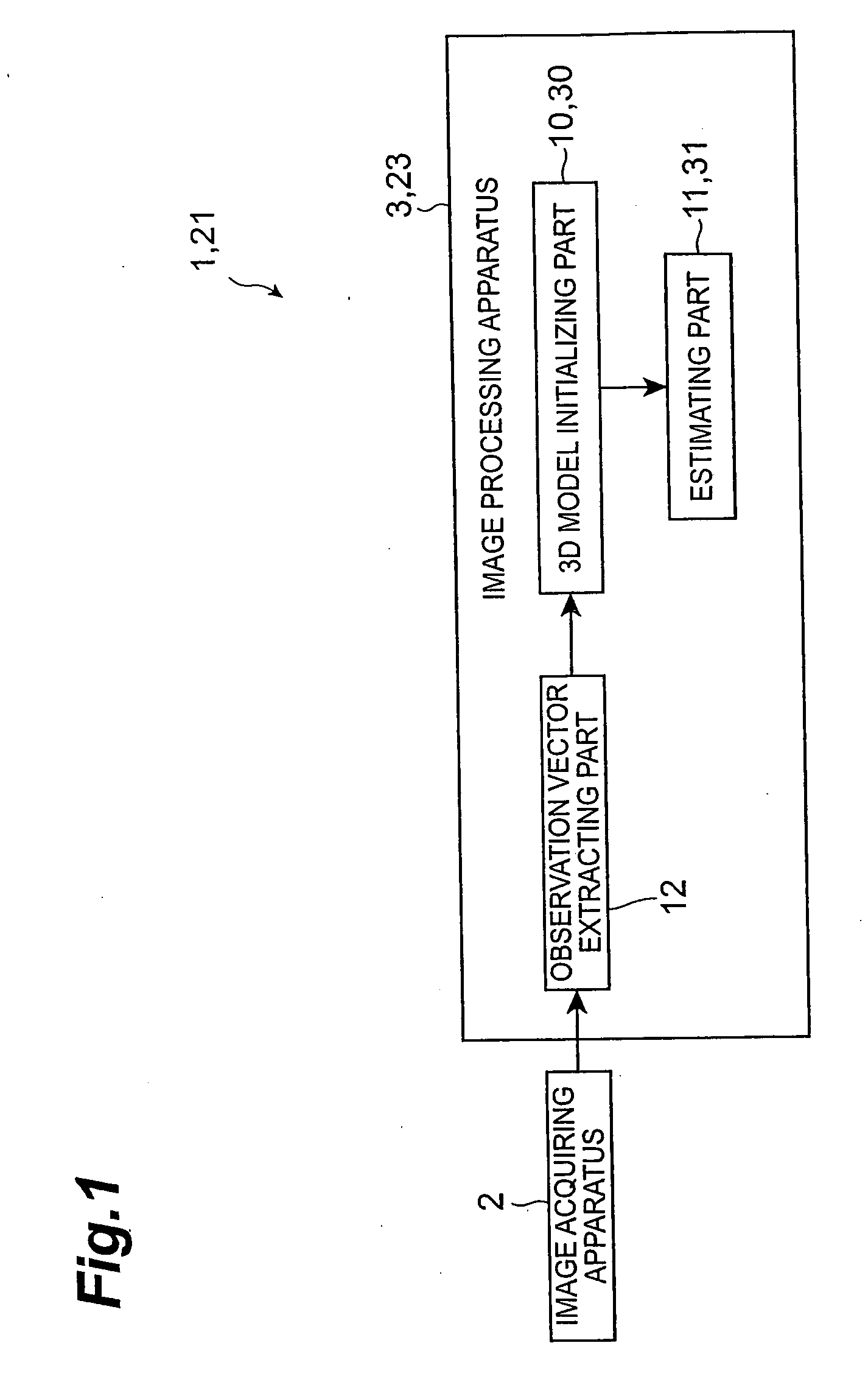
[0056] The first embodiment mode of the present invention will be described below. FIG. 1 is an illustration showing a configuration of an image processing system according to an embodiment of the present invention.

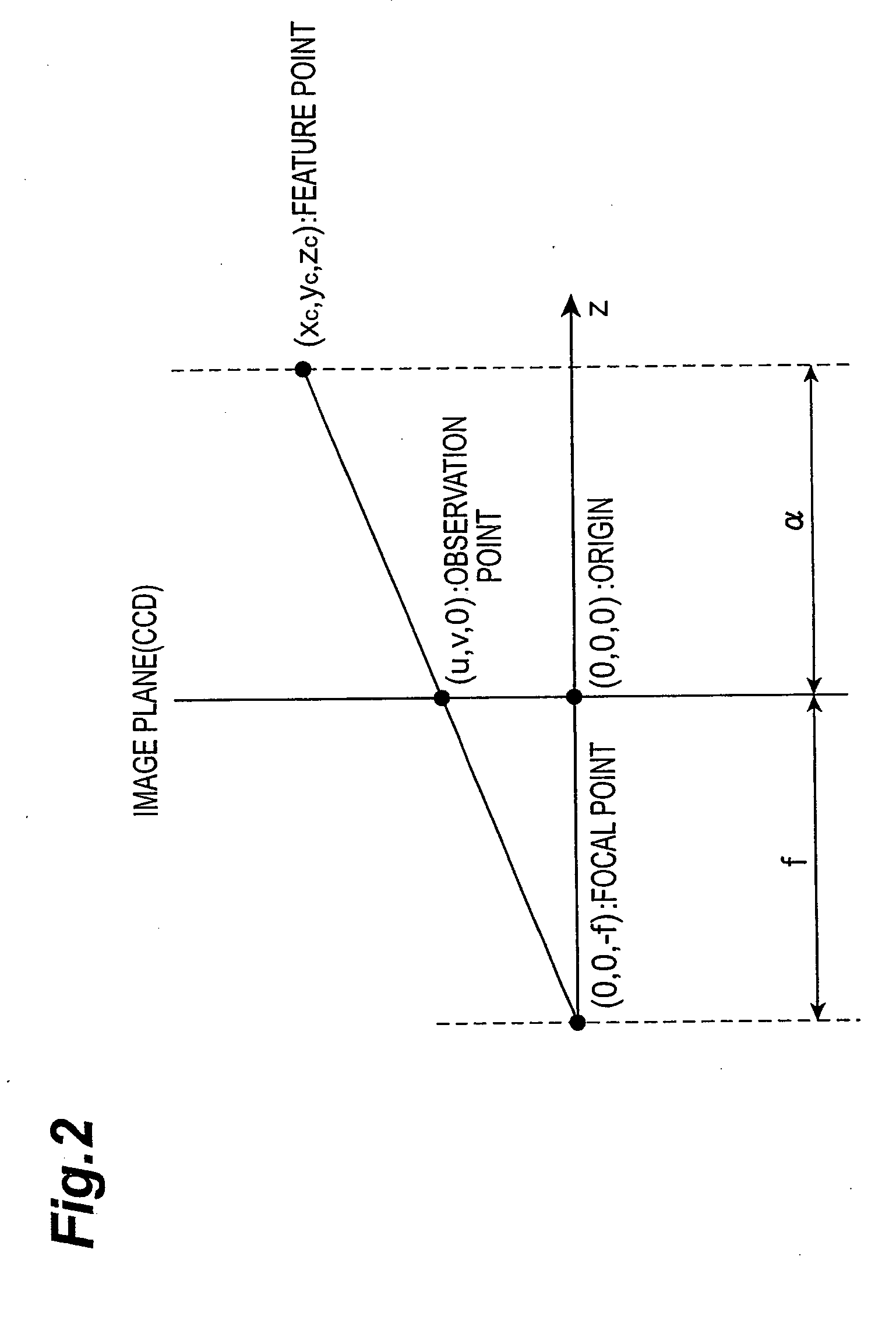
[0057] The image processing system 1 shown in FIG. 1 performs a contactless gaze estimation, using a camera model of the perspective transformation. In the image processing system 1, an image acquiring apparatus 2 is connected to an image processing apparatus 3. The image processing apparatus 3 acquires motion picture data of a face taken by the image acquiring apparatus 2. In the image processing system 1, the image processing apparatus 3 then performs an optimal estimation of the gaze from the motion picture data thus acquired. In the image processing system 1, an output device such as a monitor (not shown) is connected to the image processing apparatus 3 in order to output a process or a result of image processing according to need. The image processing system 1 p...

second embodiment

Mode

[0148] Before explaining an image processing system according to the second embodiment mode, the motion of lips of a face will be described with reference to FIGS. 15A, 15B, and 15C. FIGS. 15A, 15B, and 15C schematically show facial images indicating feature points of the lips of the face, wherein FIG. 15A shows an initial state before a motion of the face and a motion of the lips, FIG. 15B a case where only the lips have moved, and FIG. 15C a case where a motion of the face is added to the motion of the lips of FIG. 15B.

[0149] The facial image of FIG. 15A shows an initial state in which the face looks straight forward and the lips are closed. For the lips, feature points (cross marks) are set at the left and right ends and at the upper and lower center ends. The facial image of FIG. 15B shows a state in which the lips are opened while the face looks straight forward. In this manner, the feature points of the lips change with motion of the lips. The facial image of FIG. 15C sho...


PUM


Abstract

An image processing apparatus is an apparatus for determining a gaze from a motion picture of a face taken by a monocular camera, and is configured to define a 3D structure of a center of a pupil on the facial picture by a static parameter and a dynamic parameter, and to determine the gaze by estimating the static parameter and the dynamic parameter. Another image processing apparatus is an apparatus for determining a motion of a 3D object from a motion picture thereof taken by a monocular camera, and is configured to define a 3D structure of the 3D object on the picture by a rigid parameter and a non-rigid parameter, and to determine the motion of the 3D object by estimating the rigid parameter and the non-rigid parameter.

Description

TECHNICAL FIELD [0001] The present invention relates to an image processing apparatus and image processing method for performing image processing on a motion picture of a 3D object taken by a monocular camera and, more particularly, to an image processing apparatus and image processing method for estimating a motion of a 3D object from a motion picture of the 3D object. The present invention also relates to an image processing program for letting a computer execute the image processing method, and a computer-readable recording medium storing the image processing program. BACKGROUND ART [0002] There are a variety of image processing methods for detecting a local motion of a 3D object. For example, there are image processing methods of handling a face being a 3D object, as a target and detecting a pose of the face itself, a motion of each part of the face, etc. from a motion picture of the face taken by a camera. Such image processing methods include those of detecting a gaze of eyes ...

Claims


Application Information

Patent Timeline
Patent Type & Authority Applications(United States)
IPC IPC(8): G06T15/00G06T1/00G06T7/00G06T7/20
CPCG06T7/0046G06T7/2046G06T2207/30201G06T2207/10016G06T7/208G06T7/251G06T7/277G06T7/75
Inventor FUNAYAMA, RYUJIJEONG, MUN-HOOSUGI, MASAMICHI
Owner TOYOTA JIDOSHA KK
Learn More