Multistage root type pump

a multi-stage, root-type technology, applied in the field of root-type pumps, can solve the problems of long manufacturing time of the rotor at the back stage, complicated cutting operation, and reduced strength of the rotor, so as to reduce the power consumption of the pump and ease the operation of the rotor

Active Publication Date: 2007-03-01
KASHIYAMA IND
View PDF3 Cites 21 Cited by
  • Summary
  • Abstract
  • Description
  • Claims
  • Application Information

AI Technical Summary

Benefits of technology

[0014] The invention reduces power consumption of a pump and makes rotors at ease.

Problems solved by technology

However, if the axial length of rotors, i.e., the rotor thickness, is extremely thin, strength of the rotors tends to decrease thus causing deformation.
However, in traditional technology as described in patent document No. 2, there are more lobes at the back stage of the rotor, resulting in longer manufacturing time for the rotor at the back stage.
However, if the lobe number of rotors mounted on the same shaft is different, cutting operation will be complicated and it will take more time for machining.
In the case that a rotor is manufactured before fixed on the shaft, it is difficult to obtain precision of axial position.
Therefore, phase adjustment is particularly complicated, and it is also difficult to obtain precision and carry out assembly.

Method used


Image

  • Multistage root type pump
  • Multistage root type pump
  • Multistage root type pump

Examples


Embodiment Construction

[0025] The foregoing description of the invention makes it possible to reduce power consumption and enable rotor manufacture to be carried out with ease. Moreover, the discharge efficiency is increased and at the same time the rotor length is shortened.

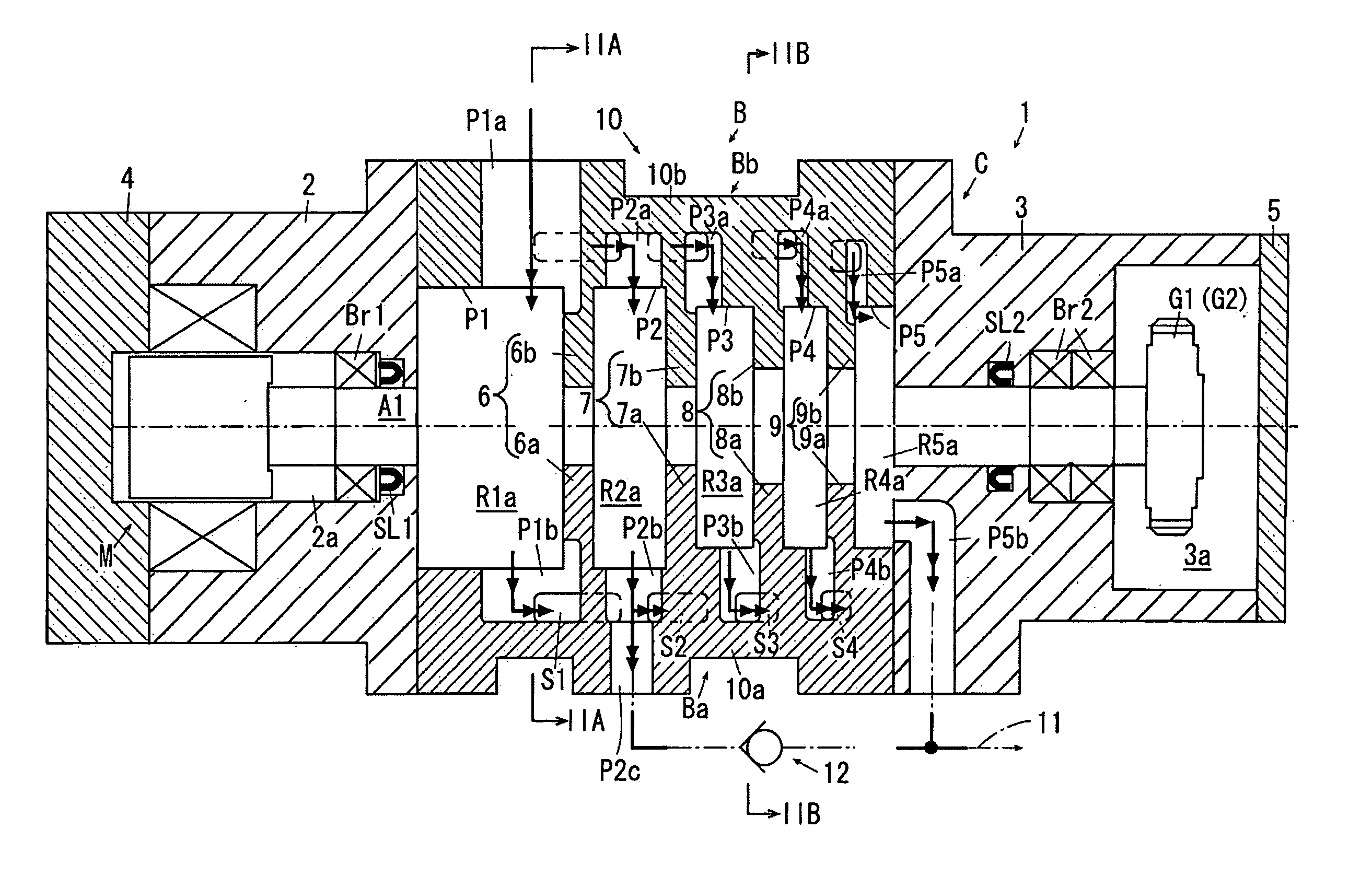
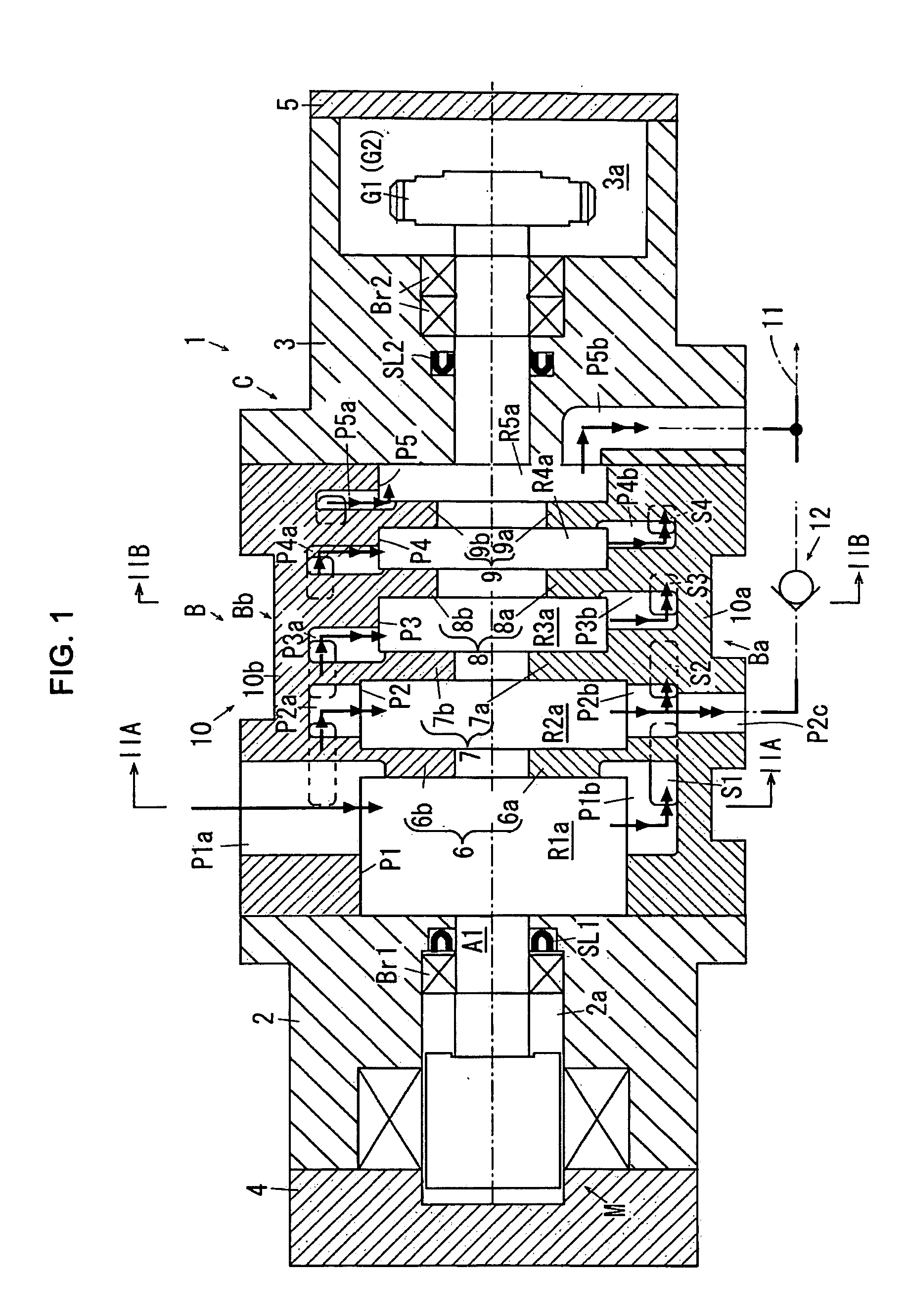
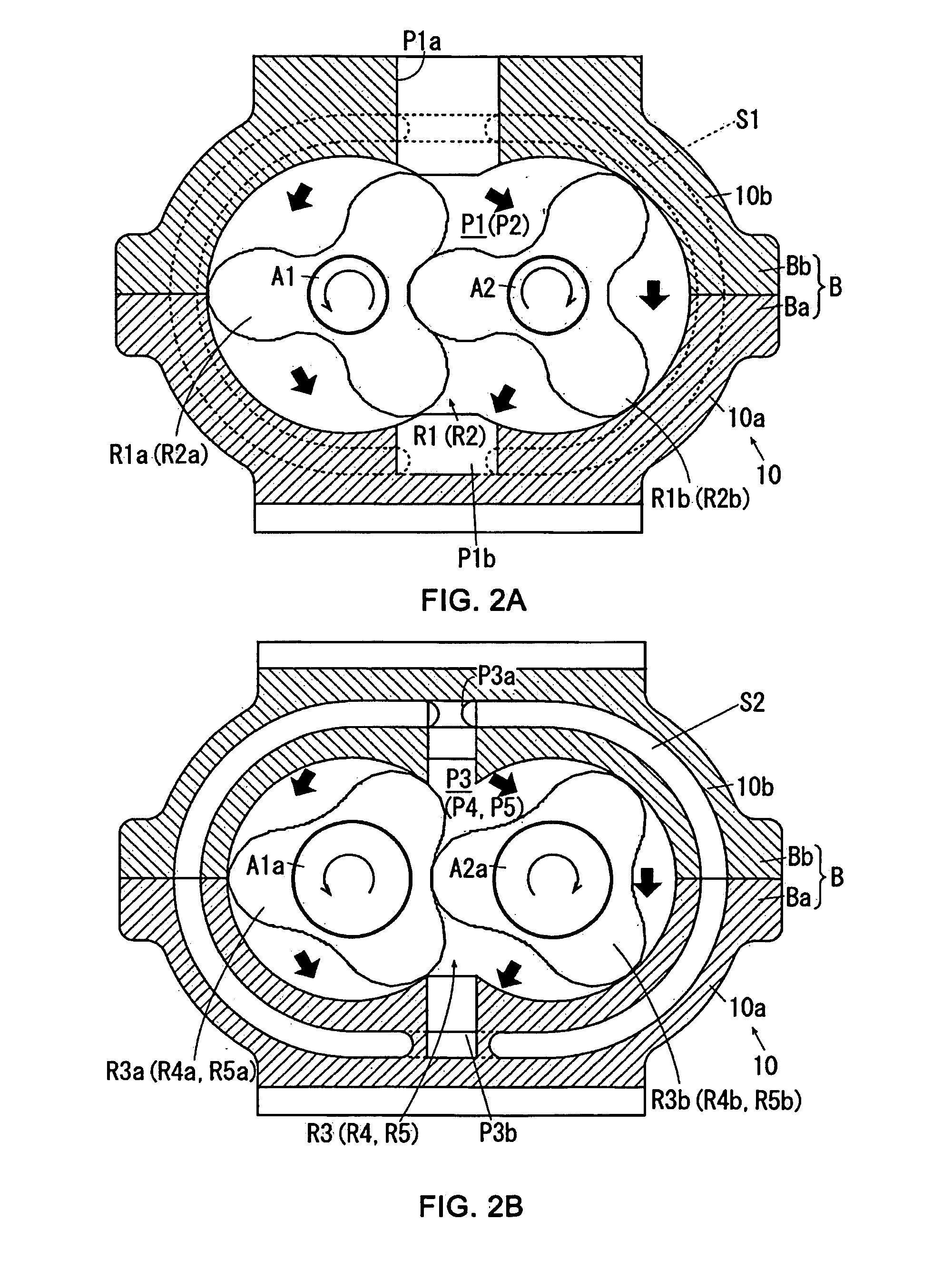
[0026] Symbols used throughout the Specification and FIGs are explained as follows. [0027]1 . . . multistage roots pump, [0028]21, 21′ . . . tooth [0029]28 . . . involute curve [0030]31, 31″ . . . tooth [0031]31a . . . arc [0032]32a . . . envelop curve [0033] A1, A2 . . . revolving shaft [0034] C . . . casing [0035] HM1, HM1″, HM2, HM2″ . . . discharge area [0036] P1˜P5 . . . pump chamber [0037] R1a, R1b, R2a, R2b, R1a′, R1b′, R2a′, R2b′ . . . upstream rotor [0038] R3a, R3b, R5a, R5b, R3a″, R3b″˜R5a″, R5b″ . . . downstream rotor

[0039] Embodiments of applications of the invention are illustrated with accompanying drawings as follows. It should be understood that application of the invention is not limited to the following embodiments...


PUM


Abstract

The invention reduces power consumption and makes rotor with ease. As illustrated in FIG. 2, a multistage roots pump (1) in the invention including upstream rotors (R1a, R1b, R2a, R2b) having multiple teeth, supported by a pair of revolving shafts (A1, A2); and downstream rotors (R3a, R3b˜R5a, R5b) having identical number of teeth (31) with the upstream rotors, supported by revolving shafts (A1, A2). The discharge area formed by the outer periphery of the downstream rotors (R3a, R3b˜R5a, R5b) and the inner periphery of the pump chambers (P1˜P5) is smaller than that of the upstream rotors (R1a, R1b, R2a, R2b).

Description

TECHNICAL FIELD [0001] The invention relates to a roots pump that transports gas by means of a pair of rotors supported by a pair of revolving shafts. In particular, it relates to a multistage roots pump wherein the rotors are designed in multiple stages. BACKGROUND [0002] Roots pumps are applied in semi-conductor manufacturing processes and liquid crystal panel manufacturing equipment includes rotors mounted on a pair of revolving shafts, respectively, to transport and discharge gas from pump chambers with sequentially decreasing volume. [0003] In order to reduce power consumption when this kind of multistage roots pump operates at maximum operating pressure, it is necessary to reduce the discharge volume at back stage (downstream side of the gas travel path) especially at the final stage. The discharge volume is determined by the volume of space formed by valleys of rotors that have multiple teeth, and the internal surface of pump chambers where rotors are mounted. [0004] With res...

Claims


Application Information

Patent Timeline
Patent Type & Authority Applications(United States)
IPC IPC(8): F04C23/00F03C4/00F01C1/30F04C2/00
CPCF04C18/084F04C18/126F04C28/26F04C25/02F04C23/001F04C18/18F04C23/00
Inventor IMAI, TOSHIOITOU, HIDEAKIMISAIZU, MASAYUKI
Owner KASHIYAMA IND
Why Eureka
Try Eureka