
Micromechanical structures having a capacitive transducer gap filled with a dielectric and method of making same

a technology of capacitive transducer and dielectric, which is applied in the direction of impedence networks, electrical apparatus, etc., can solve the problems of troublesome drawback, increased impedance needs in the 50-377 range (e.g., for antenna matching), and high bias voltage to reduce impedances. , to achieve the effect of reducing the impedance, increasing the area, and raising the efficiency of the transducer

Inactive Publication Date: 2007-03-01
RGT UNIV OF MICHIGAN
View PDF9 Cites 59 Cited by
  • Summary
  • Abstract
  • Description
  • Claims
  • Application Information

AI Technical Summary

Benefits of technology

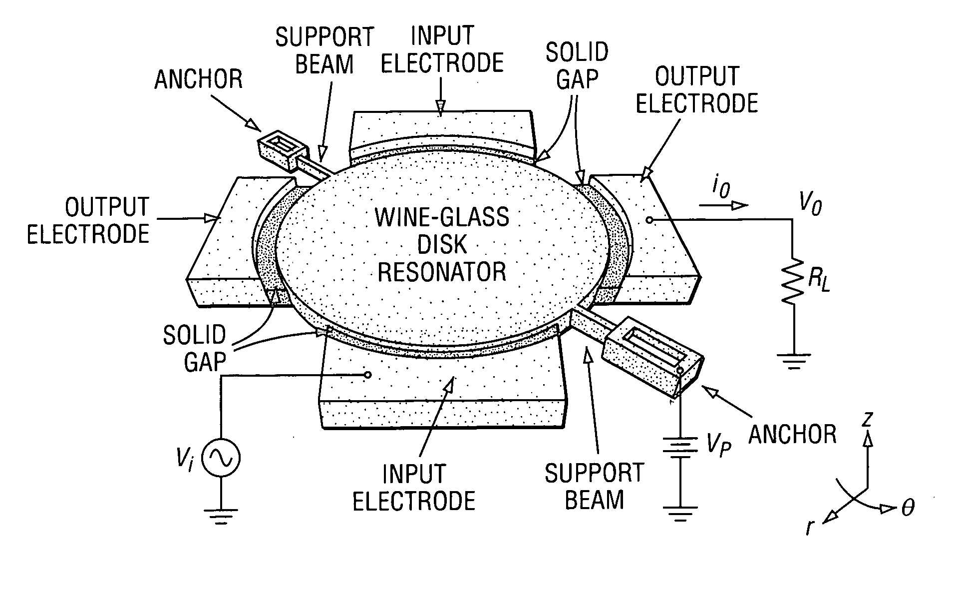
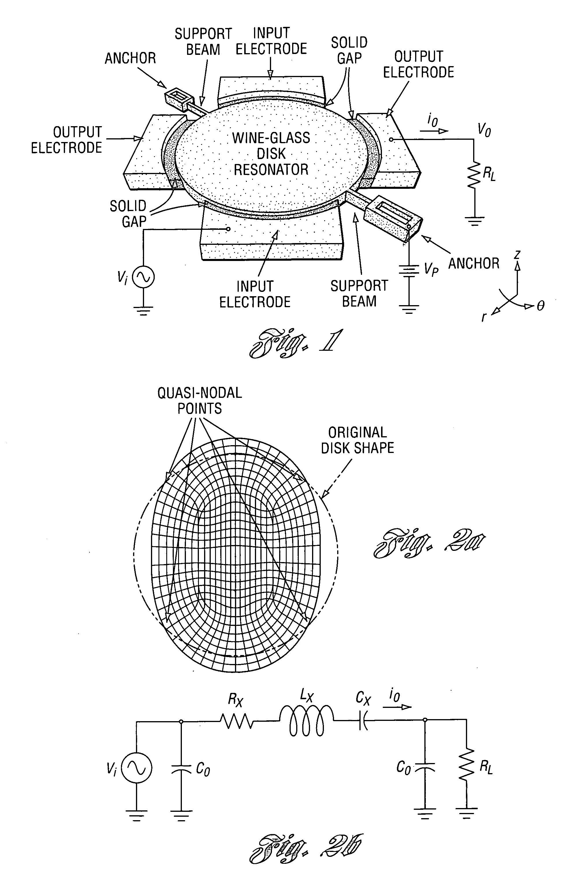
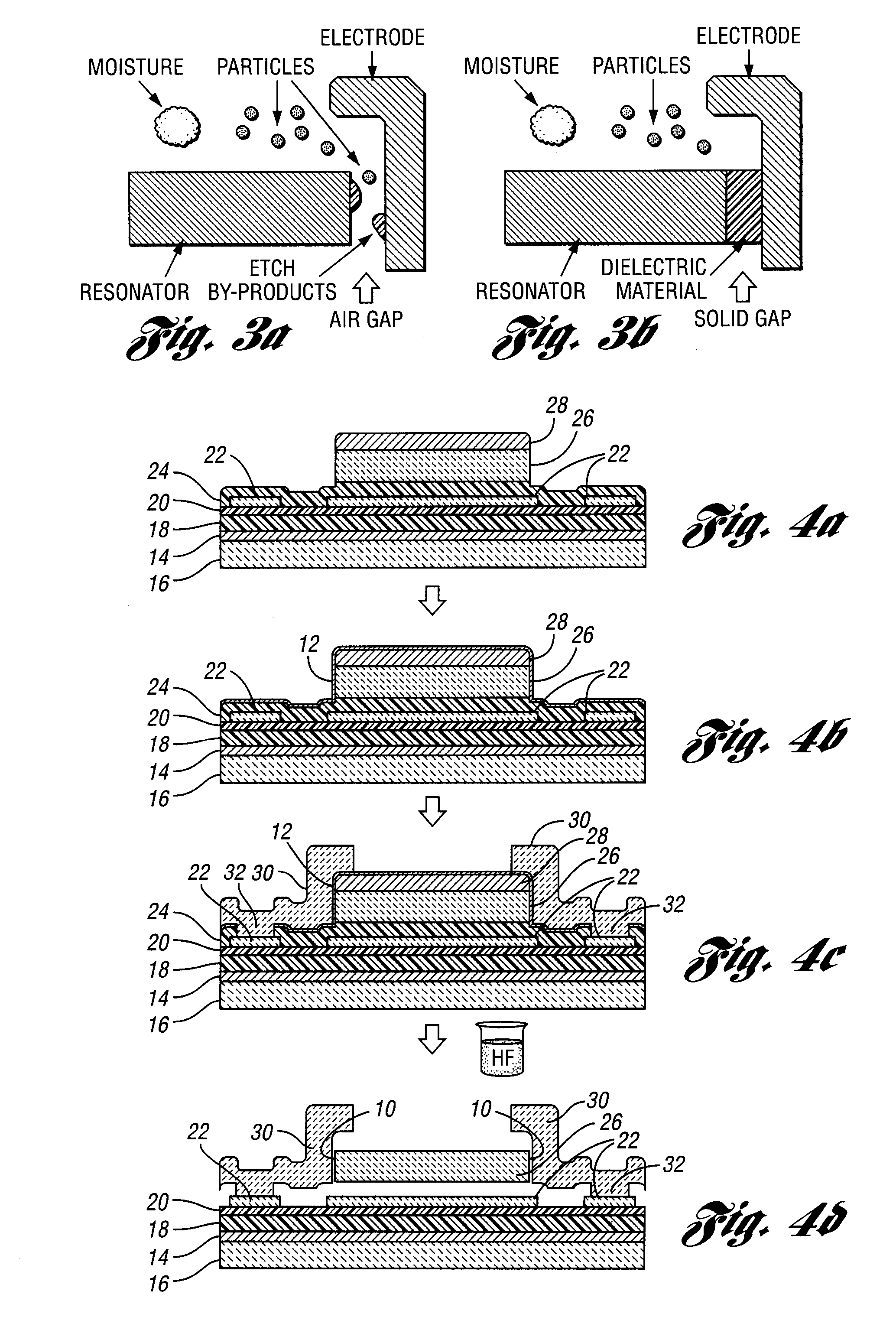
The present invention provides a method for making micromechanical structures with at least one capacitive transducer gap filled with a dielectric. By raising the permittivity of the dielectric in its capacitive gap, the efficiency of the transducer is increased without increasing the area of the capacitively transduced micromechanical resonator. The resonator and electrode define a capacitive transducer gap, and a dielectric having a higher permittivity value than air is placed in the gap to decrease the motional resistance of the resonator. The resonator may be operable in a wine-glass mode. The method includes forming the electrode structure and resonator structure on a substrate, and filling the gap with the dielectric. The thickness or length of the dielectric across the gap may correspond to a quarter-wavelength of the resonance frequency of the composite resonator-electrode structure. The invention provides a way to improve the performance of micromechanical structures with capacitive transducers.

Problems solved by technology

Although solutions now exist to many of the issues that once hindered deployment of these devices in RF front ends [4], including aging [5] [6] and temperature stability [7], the need for high bias voltages to reduce impedances, especially in the VHF and UHF ranges, still remains a troublesome drawback of this technology.
For off-chip filter applications, impedance needs in the 50-377Ω range (e.g., for antenna matching) are even more challenging, so require even high voltages.

Method used


Image

  • Micromechanical structures having a capacitive transducer gap filled with a dielectric and method of making same
  • Micromechanical structures having a capacitive transducer gap filled with a dielectric and method of making same
  • Micromechanical structures having a capacitive transducer gap filled with a dielectric and method of making same

Examples


Embodiment Construction

[0046] In one embodiment of the present invention, as described herein, VHF and UHF MEMS-based vibrating micromechanical wine-glass mode disks [8] equipped with new solid dielectric-filled capacitive transducer gaps to replace previously used air gaps have been demonstrated at 160 MHz, with Q's˜20,200 on par with those of air-gap resonators, and motional resistances (Rx's) more than 8× smaller at similar frequencies and bias conditions. (However, it is to be understood that the gaps may be filled with a dielectric fluid such as a dielectric liquid or gas without departing from the present invention.) This degree of motional resistance reduction comes about via not only the higher dielectric constant provided by a solid-filled electrode-to-resonator gap, but also by the ability to achieve smaller solid gaps than air gaps. These advantages with the right dielectric material may now allow capacitively-transduced resonators to match to the 50-377Ω impedances expected by off-chip compone...


PUM


Abstract

Micromechanical structures having at least one lateral capacitive transducer gap filled with a dielectric and method of making same are provided. VHF and UHF MEMS-based vibrating micromechanical resonators filled with new solid dielectric capacitive transducer gaps to replace previously used air gaps have been demonstrated at 160 MHz, with Q's˜20,200 on par with those of air-gap resonators, and motional resistances (Rx's) more than 8× smaller at similar frequencies and bias conditions. This degree of motional resistance reduction comes about via not only the higher dielectric constant provided by a solid-filled electrode-to-resonator gap, but also by the ability to achieve smaller solid gaps than air gaps. These advantages with the right dielectric material may now allow capacitively-transduced resonators to match to the 50-377Ω impedances expected by off-chip components (e.g., antennas) in many wireless applications without the need for high voltages.

Description

CROSS-REFERENCE TO RELATED APPLICATION [0001] This application claims the benefit of U.S. provisional application Ser. No. 60 / 712,298, filed Aug. 29, 2005.BACKGROUND OF THE INVENTION [0002] 1. Field of the Invention [0003] This invention relates to micromechanical structures having a capacitive transducer gap filled with a dielectric and method of making same. [0004] 2. Background Art [0005] The following non-patent references are referenced herein: [0006] [1] J. Wang et al., “1.51-GHz Polydiamond Micromechanical Disk Resonator with Impedance-Mismatched Isolating Support,” TECHNICAL DIGEST, IEEE INT. MICRO ELECTRO MECHANICAL SYSTEMS CONF., Maastricht, The Netherlands, January 2004, pp. 641-644. [0007] [2] S.-S. Li et al., “Micromechanical ‘Hollow-Disk’ Ring Resonators,” TECHNICAL DIGEST, IEEE INT. MICRO ELECTRO MECHANICAL SYSTEMS CONF., Maastricht, The Netherlands, January 2004, pp. 821-824. [0008] [3] J. Wang et al., “1.156-GHz Self-Aligned Vibrating Micromechanical Disk Resonator,...

Claims


Application Information

Patent Timeline
Patent Type & Authority Applications(United States)
IPC IPC(8): H03H9/00
CPCH03H3/0072H03H2009/02503H03H2009/02354H03H9/2436
Inventor NGUYEN, CLARKLIN, YU-WEILI, SHENG-SHIANXIE, YUAN
Owner RGT UNIV OF MICHIGAN
Learn More