
Ink unit containing ink and ink-contacting member

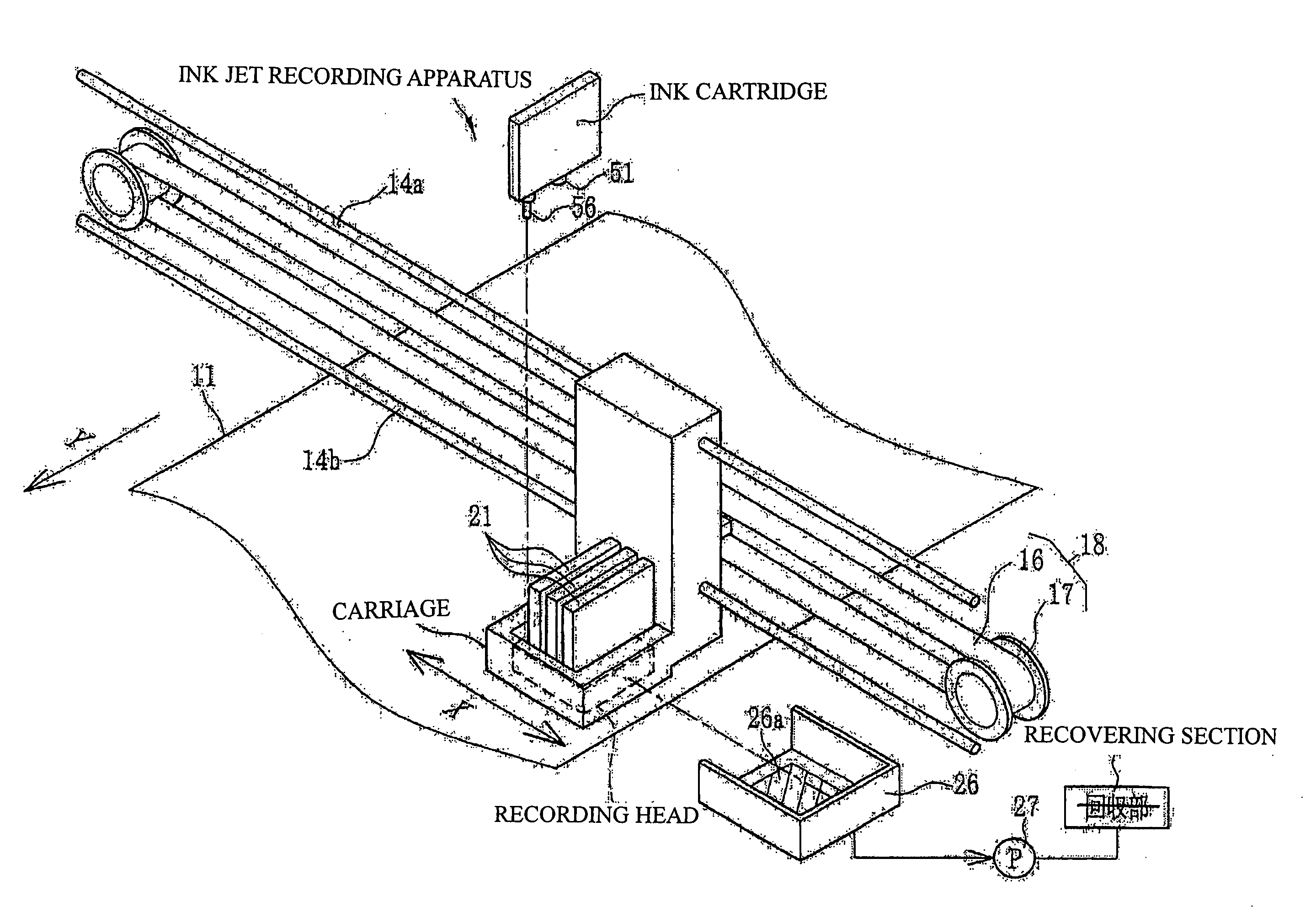
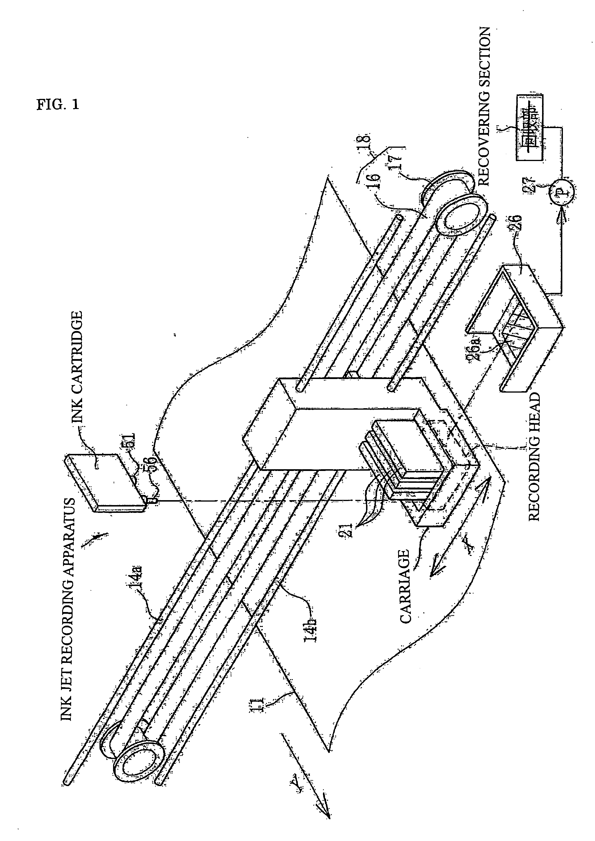
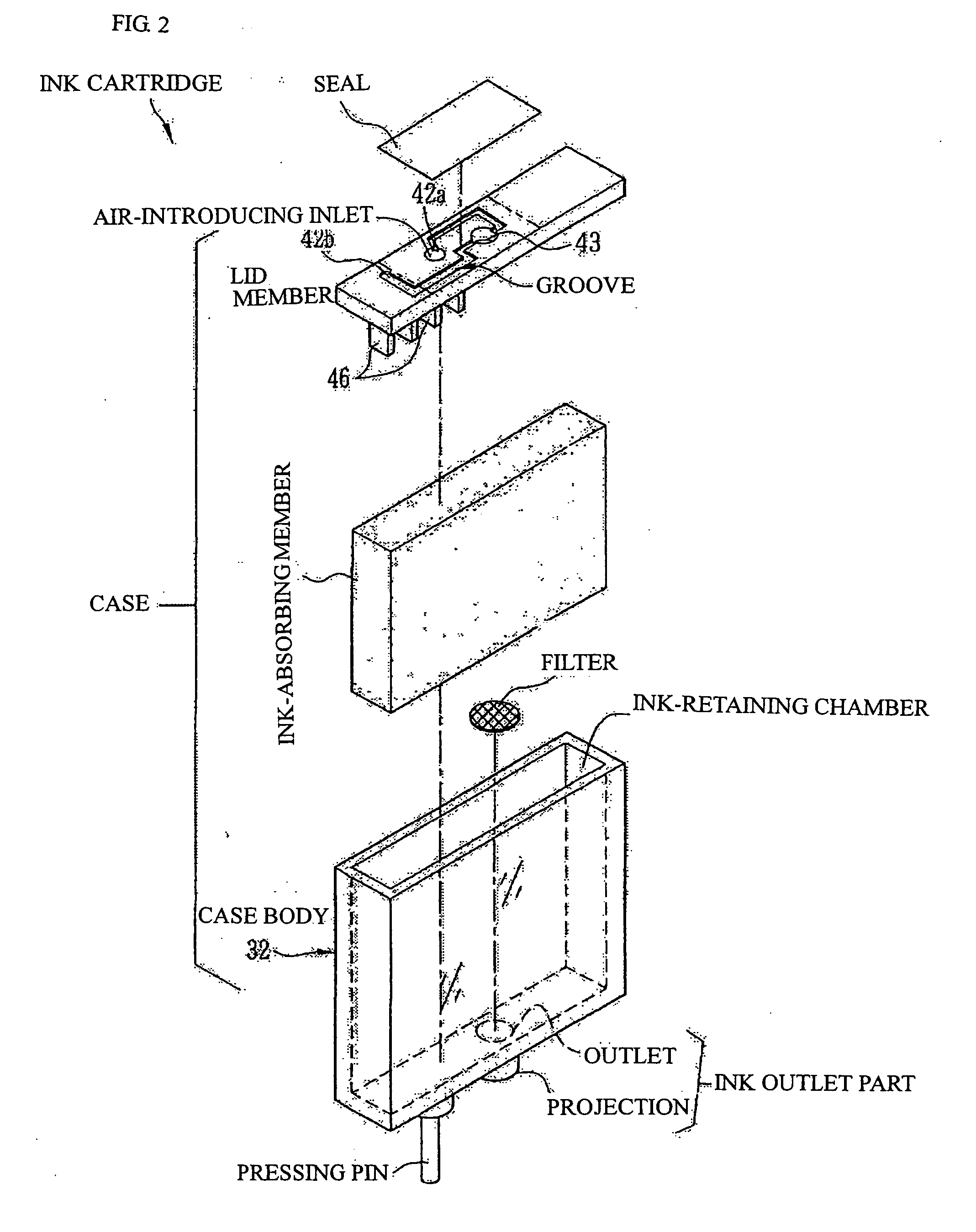
a technology of ink and ink, applied in the field of ink contact member, can solve the problems of uneven streaks and uneven density, and achieve the effect of improving the quality of ink jets and improving the accuracy of ink ejecting

Inactive Publication Date: 2007-02-22
FUJIFILM CORP
View PDF3 Cites 2 Cited by
  • Summary
  • Abstract
  • Description
  • Claims
  • Application Information

AI Technical Summary

Benefits of technology

[0010] A subject of the present invention is to improve ink-ejecting accuracy after the ink has been in contact with an ink-contacting member (in the case where the main component of the member is a polyolefin) such as an ink tank, an ink jet cartridge and / or an ink absorbing member for a long time. That is, when an ink droplet impacts a position much distant from an original position intended to impact due to a large unevenness of the volume of an ejected ink, there result uneven density and uneven streak. Hence, the subject of the invention is to improve such ink jet quality.

Problems solved by technology

That is, when an ink droplet impacts a position much distant from an original position intended to impact due to a large unevenness of the volume of an ejected ink, there result uneven density and uneven streak.

Method used


Image

  • Ink unit containing ink and ink-contacting member
  • Ink unit containing ink and ink-contacting member
  • Ink unit containing ink and ink-contacting member

Examples


example 1

(Ink-Contacting Member)

[0208] Following tanks (the same shape as BCI-3e (model No.; manufactured by Canon) were prepared by using various members as ink-contacting members.

Tank A: A polypropylene tank was molded.

[0209] Tank B: A hydrotalcite-like compound represented by Mg1-xAlx(OH)2(CO3)x / 2.mH2O (0<x≦0.5) (DHT-4A; manufactured by Kyowa Kagaku Kogyo K.K.) was mixed as a neutralizing agent in a content of 0.05% with polypropylene, and kneaded to produce pellets, followed by molding a tank using them.

Tank C: Calcium stearate was mixed in a content of 0.01% with polypropylene, and kneaded to produce pellets, followed by molding a tank using them.

Tank D: Tris(4-t-butyl-2,6-dimethyl-3-hydroxybenzyl)isocyanurate was mixed in a content of 0.2% with polypropylene, and kneaded to produce pellets, followed by molding a tank using them.

Tank E: Bis(m,p-dimethylbenzylidene)sorbitol was mixed in a content of 0.2% with polypropylene, and kneaded to produce pellets, followed by molding a...

example 2

[0216] Inks having the formulation of containing a water-soluble planar compound P-1 in a content of 2% were prepared. Whether the compound was added or not is shown in Table 17.

TABLE 17FluctuationFluctuationininWater-soluble,DropletArea ofExperimentInk-contactingPlanarImpactImpactNo.Cyan DyeMemberCompoundPositionDropletNote201ComparativeTank F:none100100Comparative Ex.Compound 1polyethylene202ComparativeTank B:none97103Comparative Ex.Compound 1polypropylene(hydrotalciteadded)203CompoundTank F:none98103Comparative Ex.101 of thepolyethyleneinvention204CompoundTank B:none8283Present Invention101 of thepolypropyleneinvention(hydrotalciteadded)205ComparativeTank F:compound101102Comparative Ex.Compound 1polyethyleneP-1(2% added)206ComparativeTank B:compound99100Comparative Ex.Compound 1polypropyleneP-1(2% added)(hydrotalciteadded)207CompoundTank F:compound100101Comparative Ex.101 of thepolyethyleneP-1(2% added)invention208CompoundTank B:compound7877Present Invention101 of thepolypropyl...

example 3

[0219] When evaluation was conducted under the conditions of Examples 1 and 2 using the cyan color materials 102, 108, 116, 136, 140, 158, 191, 192, 193, 194, 195, 196, 197 and 201 of the invention, there were shown good performance as with compound 101.


PUM

PropertyMeasurementUnit
surface tensionaaaaaaaaaa

Abstract

An ink unit comprising an ink for use in an ink jet recording apparatus; and a liquid-contacting member that contacts with the ink, wherein the ink comprises a phthalocyanine dye of a specific structure which has an oxidation potential of 1.0 V (vs SCE) or more, and wherein the major component of the ink-contacting member is a polyolefin containing [1] a specific hydrotalcite-like compound, [2] a fatty acid and / or fatty acid derivative, [3] a phenolic antioxidant having an isocyanurate skeleton or [4] an alkyl-substituted benzylidenesorbitol.

Description

BACKGROUND OF THE INVENTION [0001] 1. Field of the Invention [0002] The present invention relates to an ink-contacting member such as an ink absorbing member, an ink tank and an ink jet cartridge for use in an ink jet recording apparatus equipped with an ink-ejecting recording head and to an ink. [0003] 2. Description of the Related Art [0004] A so-called ink jet recording apparatus has been known which has a ink-ejecting type recording head wherein an ink-ejecting orifice is provided, and which allows the recording head to eject an ink as liquid droplets to deposit onto paper and record an image. In an ink jet recording apparatus is provided an ink tank, and an ink is fed from this ink tank to a recording head. As a material for a member which always comes into contact with an ink, there has been used a resin material, metallic material, rubber material or the like. Of these materials, a resin material has preferably been used from the viewpoint of cost and processability. Examples...

Claims


Application Information

Patent Timeline
Patent Type & Authority Applications(United States)
IPC IPC(8): G01D11/00B41J2/01B41J2/175C09D11/00C09D11/30
CPCC09D11/38
Inventor MORIMOTO, KIYOSHI
Owner FUJIFILM CORP
Learn More