Mixer for homodyne RF receiver

a technology of homodyne rf receiver and mixer, which is applied in the direction of demodulation, electrical equipment, transmission, etc., can solve the problems of limiting yield, increasing costs, and requiring external signal conversion, so as to improve iip3 performance and reduce the total output noise of the homodyne rf receiver

Active Publication Date: 2007-02-15
VIA TECH INC
View PDF10 Cites 11 Cited by
  • Summary
  • Abstract
  • Description
  • Claims
  • Application Information

AI Technical Summary

Benefits of technology

[0011] Another objective of the present invention is to provide a mixer for homodyne RF receiver, which has reduced noise figure.
[0012] Another objective of the present invention is to provide a mixer for homodyne RF receiver, which has improved IIP3 performance.
[0014] In one embodiment, the first transistor pair can be implemented by parallel pnp BJTs, which are parasitically formed on a MOS structure. This parallel pnp BJT is capable of improving IIP3 performance. In one embodiment, the second transistor pair may be implemented by vertical npn BJTs, which are also formed on a MOS structure. This vertical npn BJT is capable of reducing total output noise of the homodyne RF receiver.

Problems solved by technology

The heterodyne RF receiver requires not only costly discrete devices but also application of external signal conversion.
Heterodyne receivers convert RF signals from all channels into intermediate frequency (IF) signals by means of an external signal filter, and apply the IF signals to a local OSC and an external Voltage Control Oscillator (VCO) for conversion to base band signals, raising costs and limiting yield.
However, it places additional challenges to IIP3 (third order input intercept point) performance and noise figure performance.

Method used


Image

  • Mixer for homodyne RF receiver
  • Mixer for homodyne RF receiver
  • Mixer for homodyne RF receiver

Examples


Embodiment Construction

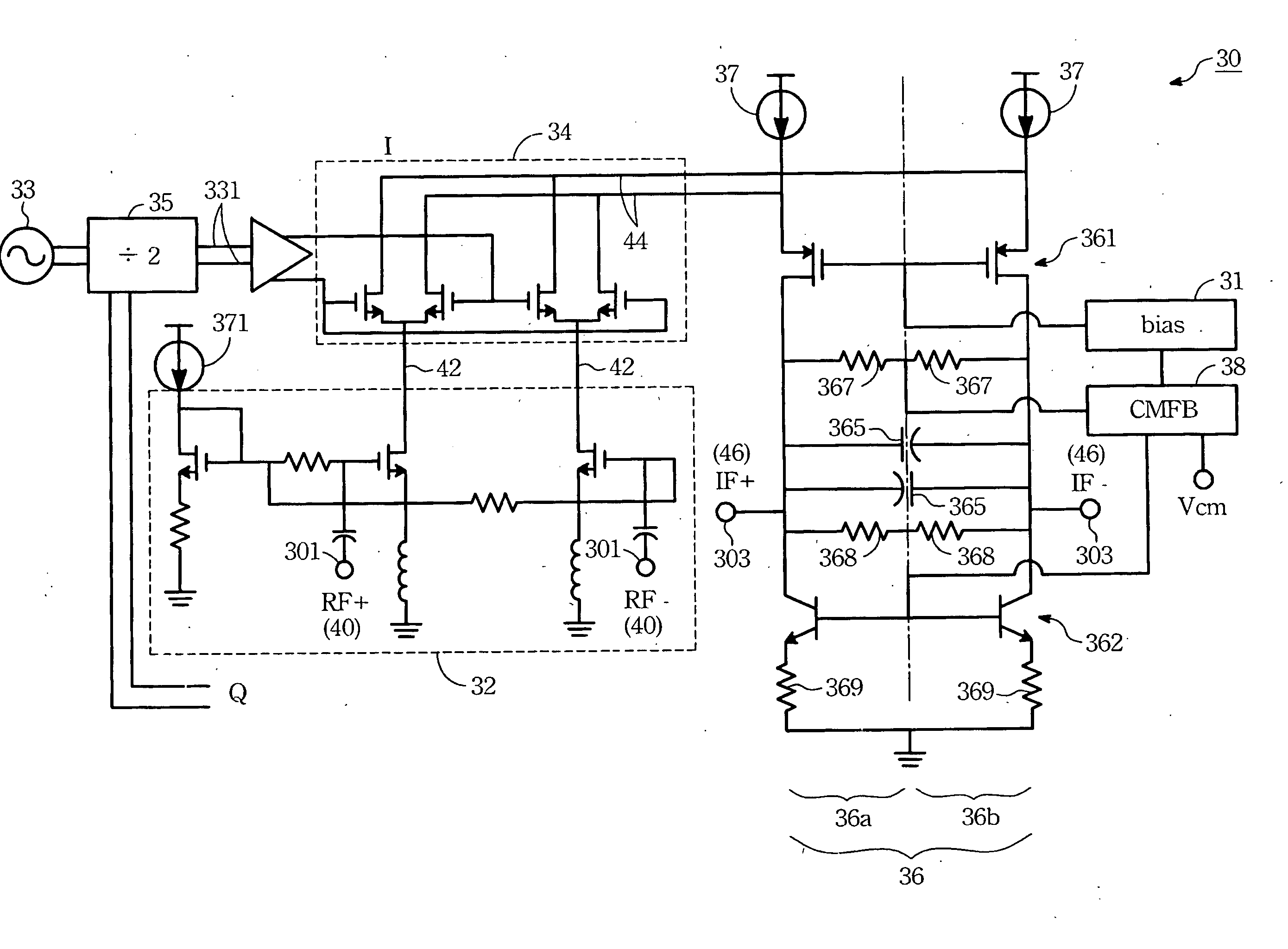
[0024] The present invention provides a mixer for a homodyne RF receiver, which is able to be made from a complimentary metal-oxide semiconductor (CMOS) process. The provided mixer comprises a gain stage, a switch stage and a load stage.

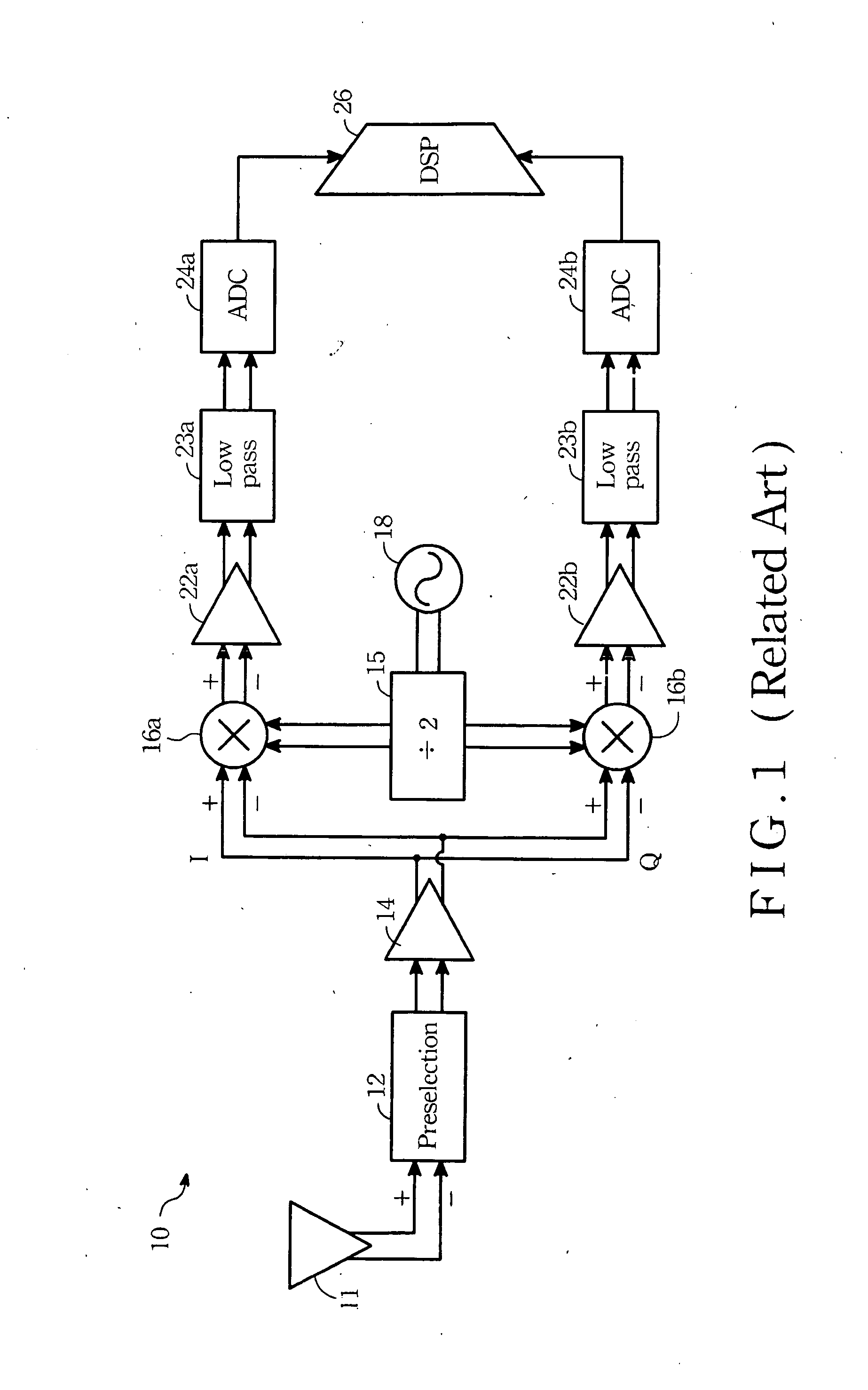
[0025] According to related prior arts, the present invention generally relates to the mixer 16a (or 16b) shown in FIG. 1. What is deserved to be mentioned is that although the implemented circuit of some typical LNA 14 is similar with the gain stage of the present invention, however, they belong to separated issues.

[0026] Please refer to FIG. 2. It is a circuit diagram according to one of the present embodiments. As mentioned above, the present mixer 30 comprises a gain stage 32, a switch stage 34 and a load stage 36. The gain stage 32 receives RF signal 40 of differential type and generates a first gained signal 42. Before the RF signal 40 is transferred to the gain stage 32, a pre-selection filter (shown as numeral 12 of FIG. 1) may be used to f...


PUM


Abstract

A mixer of a homodyne RF receiver made from a CMOS process is provided. The mixer comprises a gain stage, a switch stage and a load stage. The gain stage receives a differential-typed RF signal and generating a first gained signal. The switch stage mixes the first gained signal and a LO signal to direct down-convert into a modulated signal. The load stage comprises a first transistor, an impedance element and a second transistor. The first transistor provides a low impedance to permit the modulated signal entering the load stage. The second transistor provides a high impedance to resist signals. The load stage converts the modulated signal to a second gained signal according to a first gain coefficient of the impedance element. The first transistor is a parallel pnp BJT, and the second transistor is a vertical npn bipolar BJT.

Description

BACKGROUND OF THE INVENTION [0001] (1) Field of the Invention [0002] The present invention generally relates to a direct conversion radio frequency (RF) receiver, or a homodyne RF receiver, and particularly relates to a mixer for the homodyne RF receiver. [0003] (2) Description of the Prior Art [0004] Traditional Radio Frequency (RF) products usually employ a heterodyne RF receiver to receiving RF signal. In conventional wireless communication products, receivers usually utilize heterodyne technique, which is remarkable for its performance. Other kinds of receivers, such as the direct conversion RF receiver, the wideband IF receiver or the low IF receiver may be referred to deformed techniques of the heterodyne RF receiver. [0005] The heterodyne RF receiver requires not only costly discrete devices but also application of external signal conversion. Heterodyne receivers convert RF signals from all channels into intermediate frequency (IF) signals by means of an external signal filte...

Claims


Application Information

Patent Timeline
Patent Type & Authority Applications(United States)
IPC IPC(8): H04B1/26H04B1/28
CPCH03D7/145H03D2200/0033H04B1/30H03D7/165
Inventor TSENG, YING-CHECHENG, NEAN-CHU
Owner VIA TECH INC
Why Eureka
Try Eureka