
Method and apparatus for mounting a heat sink in thermal contact with an electronic component

a technology of heat sink and electronic component, which is applied in the direction of electrical apparatus construction details, basic electric elements, solid-state devices, etc., can solve the problems of reducing the performance of electronic components, reliability, life expectancy, and deflection of printed circuit boards, so as to reduce stress and reduce the risk of bending, the cross-section of printed circuit boards of relatively thick cross-section is typically less compliant than the cross-section of printed circuit boards

Active Publication Date: 2007-02-15
IBM CORP
View PDF27 Cites 57 Cited by
  • Summary
  • Abstract
  • Description
  • Claims
  • Application Information

AI Technical Summary

Benefits of technology

[0011] The present invention provides an enhanced mounting mechanism for holding a heat sink in thermal contact with an electron...

Problems solved by technology

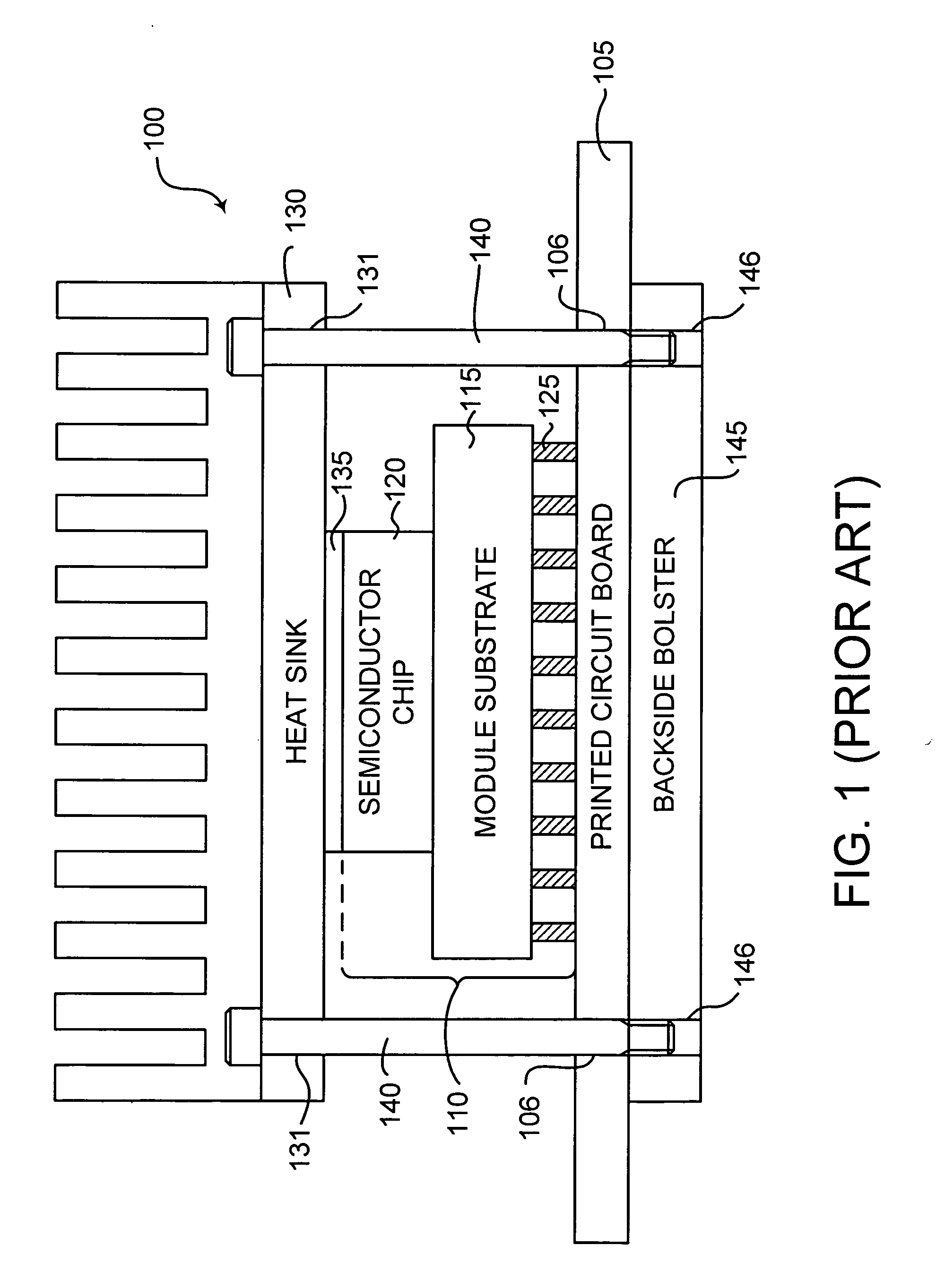
Excessive heat degrades electronic component performance, reliability, life expectancy, and can even cause failure.
Unfortunately, deflection of printed circuit board 105 will not always provide the necessary compliance to decrease stresses on electronic component 120.
Printed circuit boards of relatively thick cross-section are typically less compliant than printed circuit boards of thinner cross-section.
Consequently, the necessary compliance often cannot be achieved by deflecting relatively thick cross-section printed circuit boards.
Moreover, the resulting stresses on the printed circuit board upon deflection can lead to catastrophic failure of solder joints and conductor traces on the printed circuit board.
In addition, if the bare die module has a relatively large area, the concave-arc that results upon deflection of the printed circuit board can put the solder joints of the bare die module under unacceptable tension stresses.

Method used


Image

  • Method and apparatus for mounting a heat sink in thermal contact with an electronic component
  • Method and apparatus for mounting a heat sink in thermal contact with an electronic component
  • Method and apparatus for mounting a heat sink in thermal contact with an electronic component

Examples


Embodiment Construction

[0025] 1. Overview

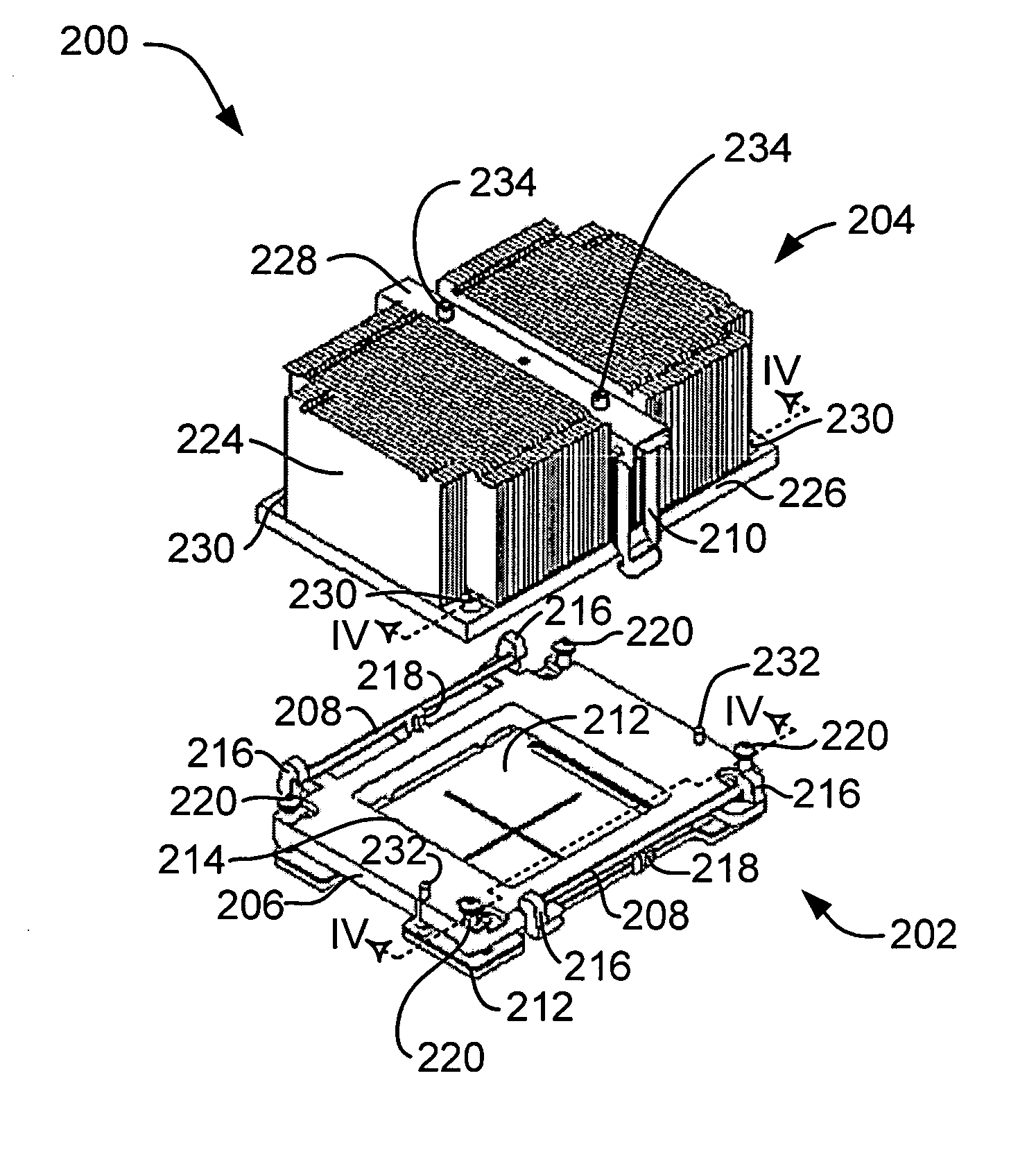
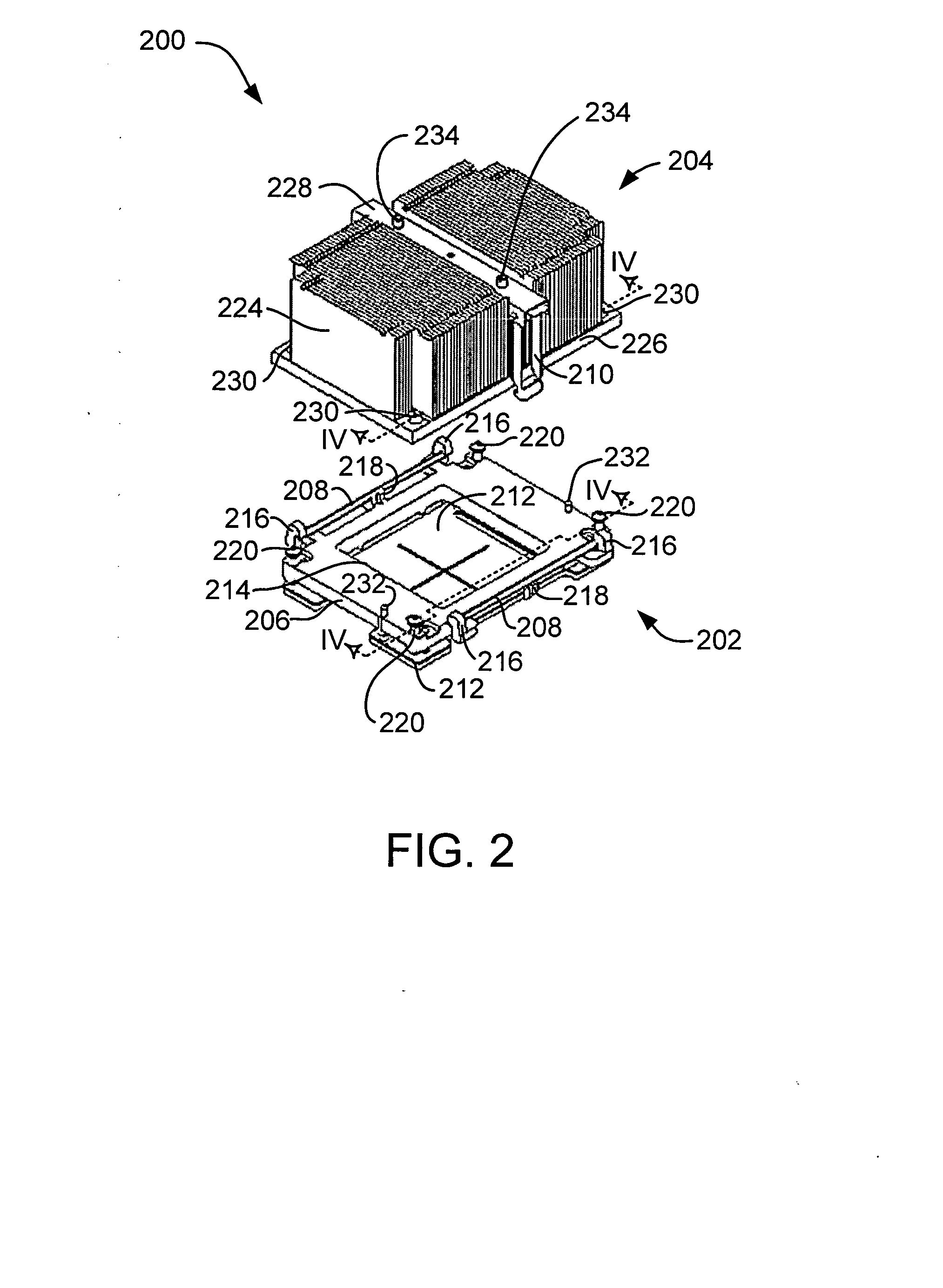
[0026] In accordance with the preferred embodiments of the present invention, a heat transfer apparatus comprises a load frame having load springs and an open region that exposes an electronic component. The load frame is mounted to a printed circuit board on which the electronic component is mounted. A heat sink assembly is disposed on the load frame and has a main body in thermal contact with the electronic component through a thermally conductive material. The heat sink assembly has load arms for engaging the load springs. A load plate extends between the load arms and has an actuation element operative to displace the main body relative to the load plate and thereby resiliently deform the load springs and produce a load force that compresses the thermally conductive material to achieve a desired thermal interface gap between the main body and the electronic component. Non-influencing fasteners secure the heat sink to the load frame and maintain the desired the...


PUM

PropertyMeasurementUnit
Lengthaaaaaaaaaa
Forceaaaaaaaaaa
Creep rateaaaaaaaaaa

Abstract

A heat transfer apparatus comprises a load frame having load springs and an open region that exposes an electronic component. The load frame is mounted to a printed circuit board on which the electronic component is mounted. A heat sink assembly is disposed on the load frame and has a main body in thermal contact with the electronic component through a thermally conductive material. The heat sink assembly has load arms for engaging the load springs. A load plate extends between the load arms and has an actuation element operative to displace the main body relative to the load plate and thereby resiliently deform the load springs and produce a load force that compresses the thermally conductive material to achieve a desired thermal interface gap between the main body and the electronic component. Non-influencing fasteners secure the heat sink to the load frame and maintain the desired thermal interface gap.

Description

BACKGROUND OF THE INVENTION [0001] 1. Field of Invention [0002] The present invention relates in general to the field of electronic packaging, and in particular to electronic packaging that removes heat from an electronic component. [0003] 2. Background Art [0004] Electronic components, such a microprocessors and integrated circuits, must operate within certain specified temperature ranges to perform efficiently. Excessive heat degrades electronic component performance, reliability, life expectancy, and can even cause failure. Heat sinks are widely used for controlling excessive heat. Typically, heat sinks are formed with fins, pins or other similar structures to increase the surface area of the heat sink and thereby enhance heat dissipation as air passes over the heat sink. In addition, it is not uncommon for heat sinks to contain high performance structures, such as vapor chambers and / or heat pipes, to further enhance heat transfer. Heat sinks are typically formed of metals, such ...

Claims


Application Information

Patent Timeline
IPC IPC(8): H05K7/04H05K7/20
CPCH01L23/4006H01L2023/405H01L2023/4081H01L2924/3011Y10T29/49826H01L2924/0002Y10T29/4913H01L2924/00
Inventor COLBERT, JOHN LEEECKBERG, ERIC ALANHAMILTON, ROGER DUANEHOFFMEYER, MARK KENNETHMIKHAIL, AMANDA ELISA ENNISSINHA, ARVIND KUMAR
Owner IBM CORP
Learn More