Electrochemistry and electrogenerated chemiluminescence with a single faradaic electrode
a faradaic electrode, electrochemical technology, applied in the direction of instruments, material electrochemical variables, assay labels, etc., can solve the problems of increasing the difficulty of separating the working electrode from the counter electrode, and the assay throughpu
- Summary
- Abstract
- Description
- Claims
- Application Information
AI Technical Summary
Problems solved by technology
Method used
Image
Examples
example 1
Measurement of Faradaic Current at a Working Electrode in an Electrochemical Cell having a Capacitive Counter Electrode
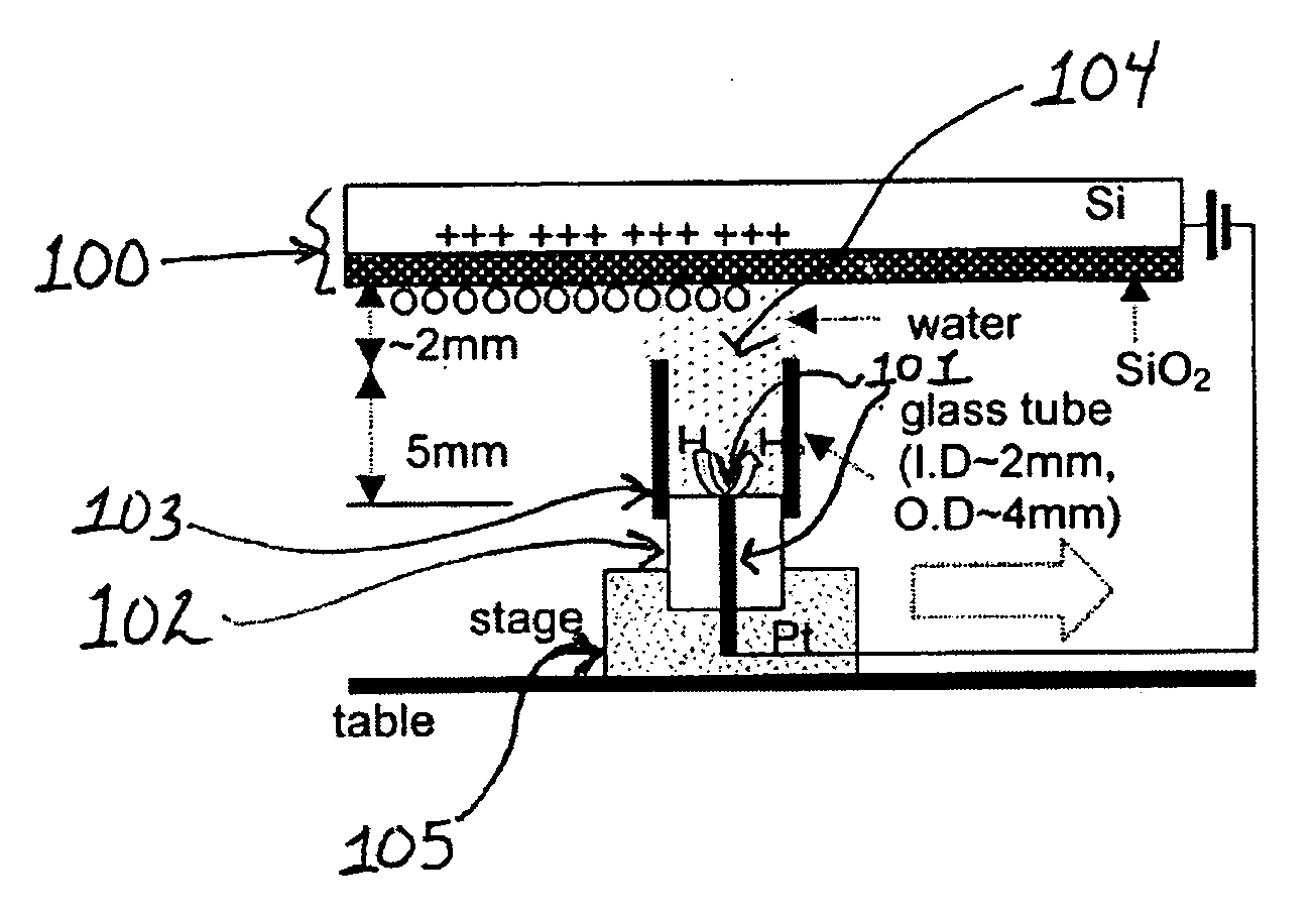
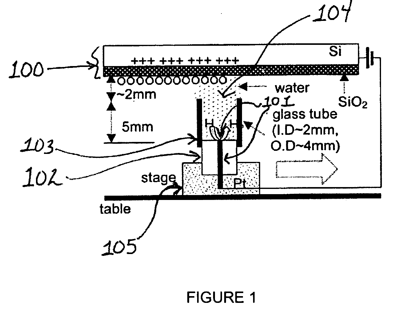
[0270] A 25 μm diameter Pt wire (101) sealed in a glass UME (102) tip served as the faradaic electrode and contacted a few mm diameter drop of deionized (MilliQ) water placed on the SiO2 film (500 nm thick) on a single crystal Si wafer (100) with a thin insulating film of SiO2 functioning as the capacitive electrode. Samples of SiO2 / Si were prepared at SEMATECH (Austin, Tex.) by chemical vapor deposition without further treatment. In experiments where a water drop was moved along the SiO2 surface under a bias as shown schematically in FIG. 1, a 2 mm diameter glass tube (103) was attached to the 25 μm Pt tip with parafilm to avoid water leakage. The tube was slightly over filled so that a water drop (104) was formed at its top to contact the SiO2 surface and the drop could be moved horizontally to continuously make contact with a fresh part of the oxide surface. The...
example 2
Measurement of Faradaic Current at a Moving Working Electrode in an Electrochemical Cell having a Capacitive Counter Electrode
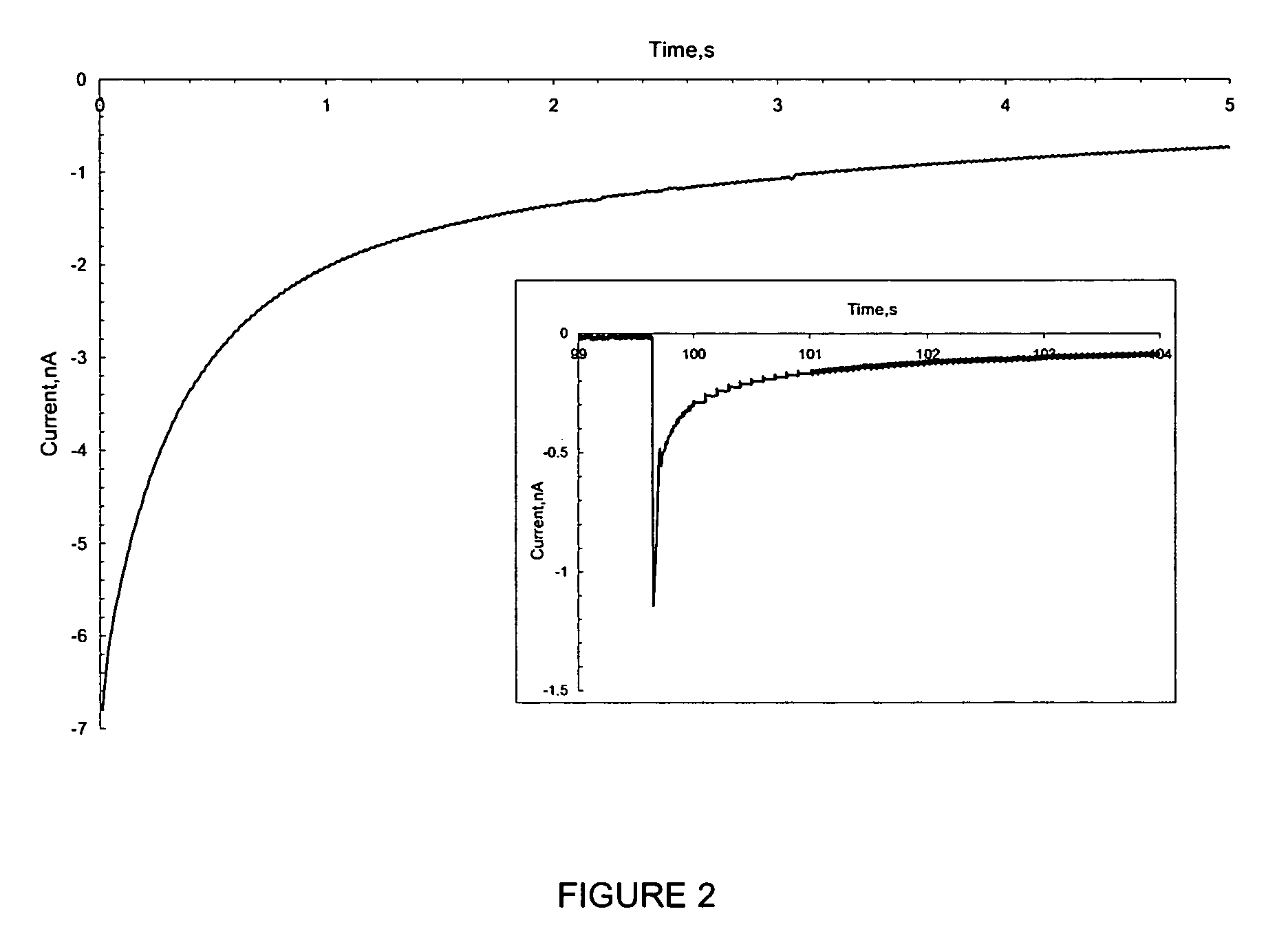
[0272] Using the set up described in Example 1, the water drop (104) and associated Pt UME (101) were moved across the SiO2 surface under a constant bias. Before movement, a bias of −1 V was applied to the tip and the surface became fully charged. Then, the tip was moved laterally by pushing the translation stage (105) manually at a rate of roughly 1 cm / s over a distance of about 0.5 to 4 cm without disconnecting the bias and the current increased as shown in FIG. 3. The current reached a steady state at the nA level, which was maintained by continuous exposure to fresh surface. The current did not drop until the movement ended and the charging at this location approached saturation (FIG. 3). The contact area of the SiO2 electrode and the water drop remained essentially constant during the lateral tip movement. The steady state current depended on how fast t...
example 3
Measurement of ECL at in an Electrochemical Cell Having a Capacitive Counter Electrode
[0276] A 250 μm Pt wire was bent at a right angle, coated with epoxy cement and then polished to expose an area of about 0.02 mm2 facing a photomultiplier tube (PMT, R4220p, Hamamatsu, Bridgewater, N.J.). A piece of Si with an area of ˜40 cm2 and coated with a ˜50 nm thick SiO2 film was used the counter electrode in an aqueous solution containing 0.5 mM Ru(bpy)32+[tris(2,2′-bipyridine)ruthenium(II)] in 0.10 M tri-n-propylamine (TPA) with 0.10 M Tris / 0.10 M LiClO4 buffer (pH=8). An Autolab potentiostat (Model PGSTAT100, EcoChemie, Utrecht, The Netherlands) was used to control the applied potential with Pt as the working electrode and the Si back contact as the counter electrode. The reference electrode input on the potentiostat was connected to the counter electrode. The ECL emission and the current were recorded simultaneously during the measurement. Potential pulses from 1.4 V (30 s) to −0.5 V (2...
PUM
| Property | Measurement | Unit |
|---|---|---|
| Temperature | aaaaa | aaaaa |
| Time | aaaaa | aaaaa |
| Pore size | aaaaa | aaaaa |
Abstract
Description
Claims
Application Information
 - R&D
- Intellectual Property
- Life Sciences
- Materials
- Tech Scout
- Unparalleled Data Quality
- Higher Quality Content
- 60% Fewer Hallucinations
Browse by: Latest US Patents, China's latest patents, Technical Efficacy Thesaurus, Application Domain, Technology Topic, Popular Technical Reports.
© 2025 PatSnap. All rights reserved.Legal|Privacy policy|Modern Slavery Act Transparency Statement|Sitemap|About US| Contact US: help@patsnap.com


