Eureka AIR delivers breakthrough ideas for toughest innovation challenges, trusted by R&D personnel around the world.

Ethanol recovery process

a technology of ethanol recovery and recovery process, which is applied in the direction of separation process, reverse osmosis, membranes, etc., can solve the problems of near-zero net greenhouse gas emissions, design failure, and insufficient fermentable sugar content of materials that comprise feedstock used to produce bioethanol, etc., to achieve low permeation pressure, simplify equipment, and high maintenance components

Active Publication Date: 2007-02-08
MEMBRANE TECH & RES
View PDF4 Cites 160 Cited by
  • Summary
  • Abstract
  • Description
  • Claims
  • Application Information

AI Technical Summary

Benefits of technology

[0034] Ethanol and other light alcohols can be made and recovered from all of these materials more cost-effectively by the present process than by prior art processes.
[0046] The ability of the dephlegmation step to lower the permeate pressure is often sufficient to obviate the need for a vacuum pump on the permeate side, thereby simplifying the equipment and reducing the need for relatively high maintenance components to operate the membrane separation step.
[0054] The invention is applicable to alcohol, especially ethanol, production at all scales, but is particularly well suited for small-scale, localized plants with production of less than about 5 or 10 million gallons of alcohol per year. The invention makes possible distributed ethanol production from the thousands of relatively small local sources of biomass and sugar-containing streams that exist throughout rural America and the world.

Problems solved by technology

It is compatible with current and future transportation systems and results in near-zero net greenhouse gas emissions.
The design proved unsuccessful however, as high ethanol taxes led people to favor gas.
However, most ethanol production today is being done at large centralized processing facilities, because the methods currently used are economically viable only at capacities of 30 million gallons per year or more.
In some cases, the raw materials that comprise the feedstock used to produce bioethanol may not contain any or sufficient fermentable sugars, so various conversion techniques may be used to obtain fermentable sugars, particularly from cellulosic or lignocellulosic materials.

Method used


Image

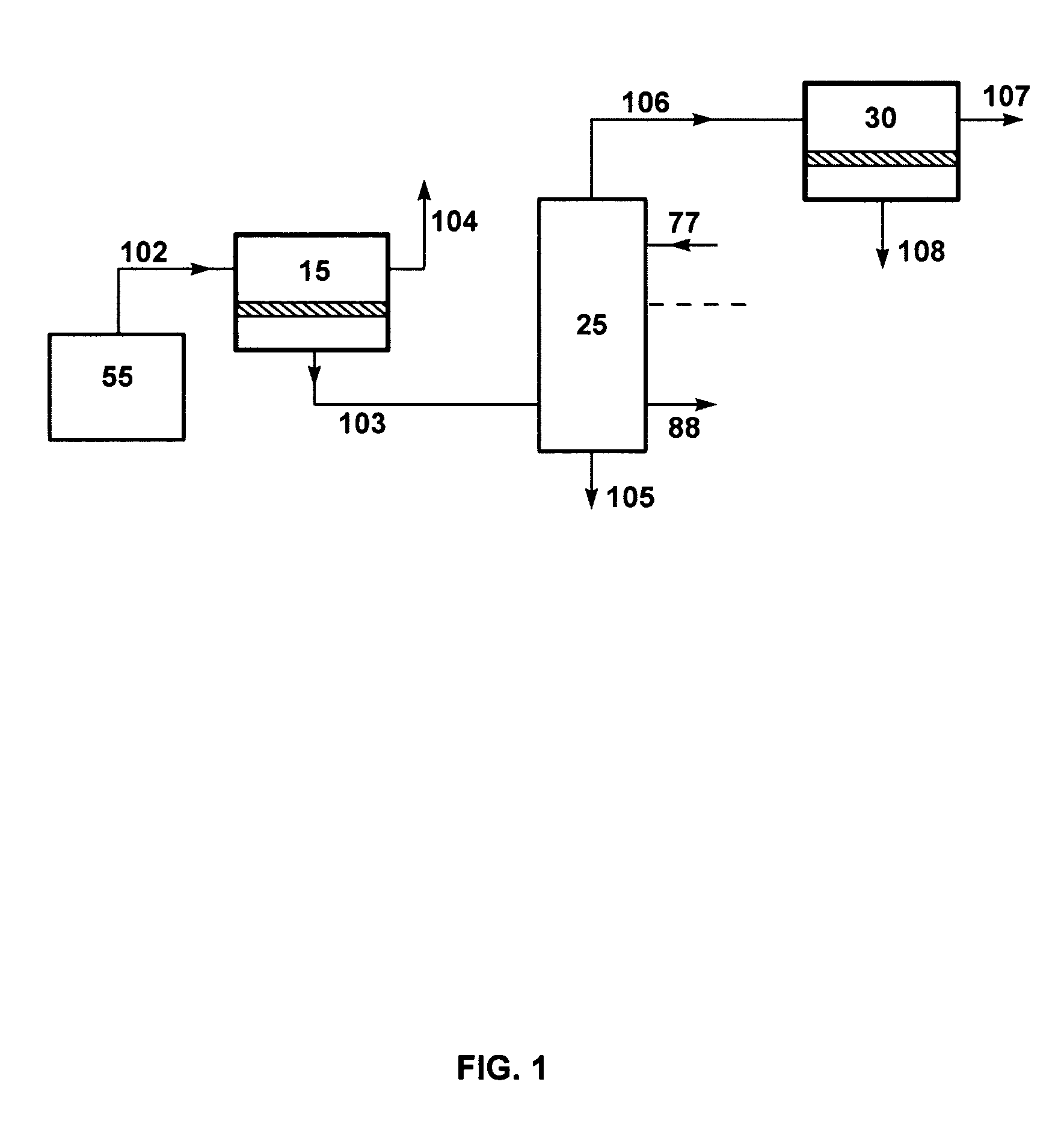
  • Ethanol recovery process
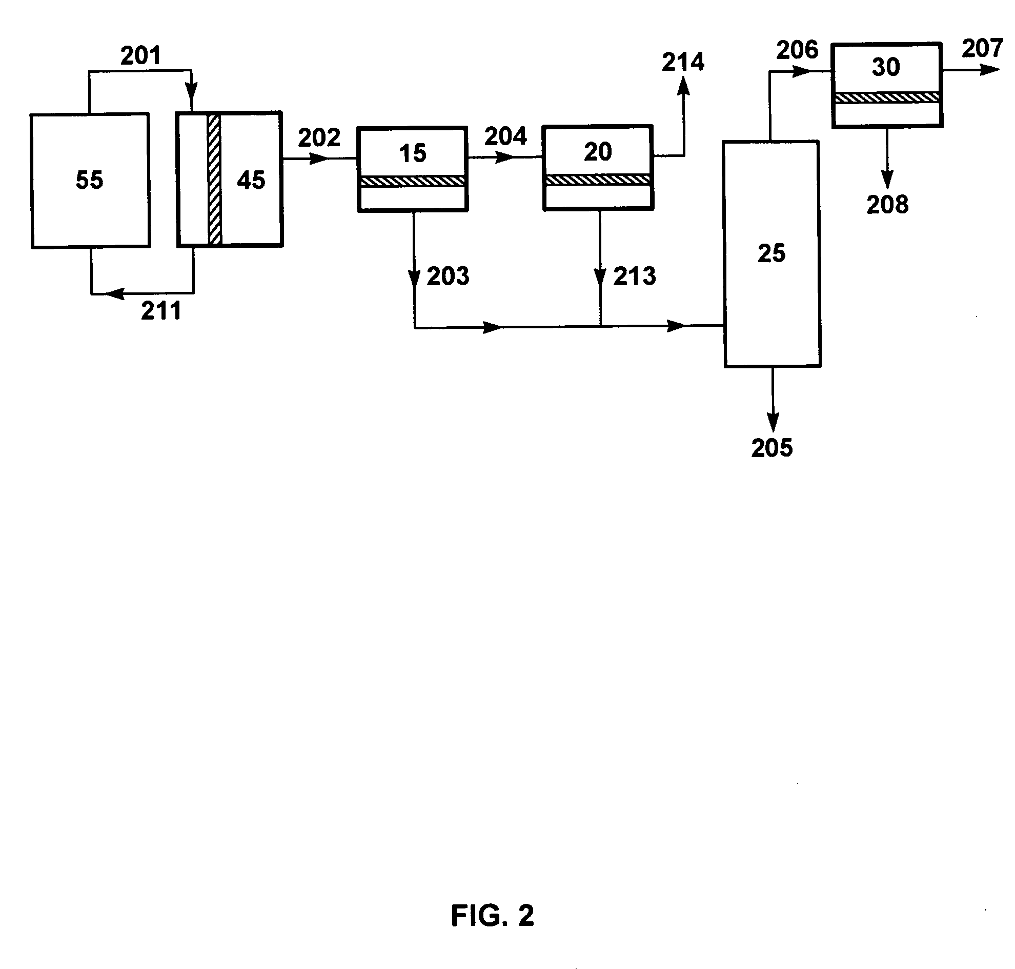
  • Ethanol recovery process
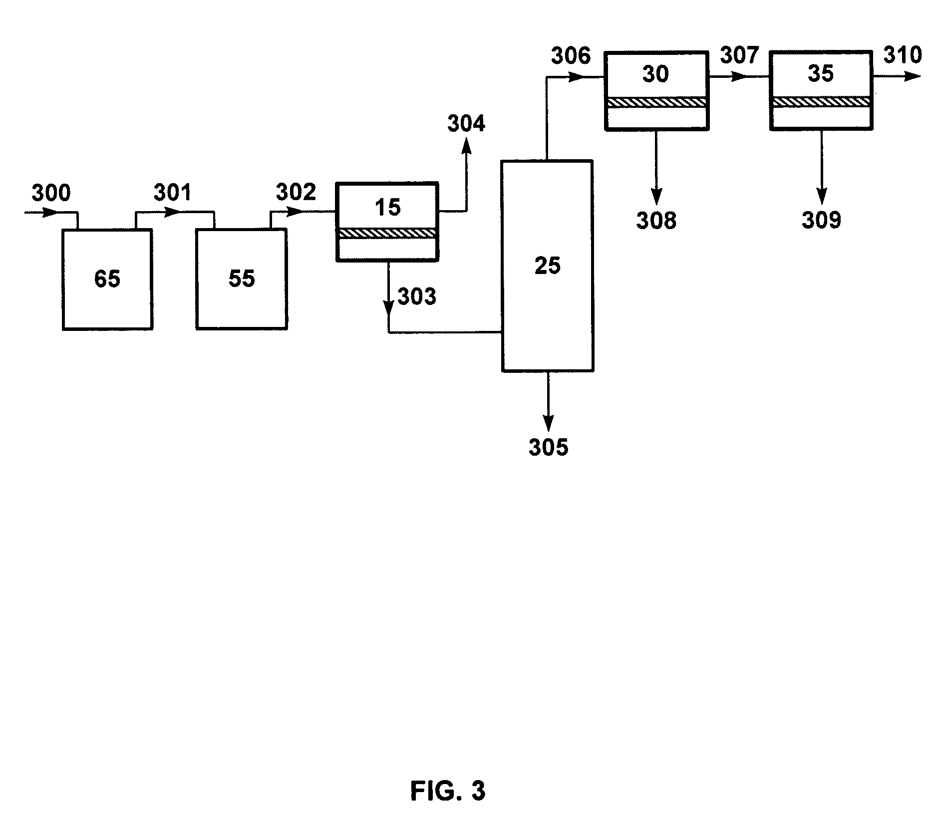
  • Ethanol recovery process

Examples


example 1

Ethanol Removal with Composite Membranes

[0180] Composite membranes were prepared using standard casting and coating techniques. Polyvinylidene fluoride (PVDF) was used as the support in each case.

[0181] One membrane was prepared using polydimethylsiloxane (PDMS) as the selective layer. Other membranes were prepared using silicalite-1 zeolites available from Zeolyst International (P.O. Box 830, Valley Forge, Pa., 19482) in a PDMS polymer matrix as the selective layer. All membranes were prepared by solution-coating the selective layer onto the support layer to generate the following samples: [0182] Sample 1: PDMS on PVDF [0183] Sample 2: A single coat of 20 wt % solution containing polydimethylsiloxane (PDMS) and zeolite in a ratio of 1:1 was applied to PVDF. The thickness of the selective layer was about 80 μm. [0184] Sample 3: A double coat of 20 wt % solution containing PDMS and zeolite in a ratio of 2:1 was applied to PVDF. The thickness of the selective layer was about 150 μm....

example 2

Ethanol Dehydration with Perfluorinated Composite Membranes

[0187] Commercial membranes were purchased and composite membranes were prepared using standard casting and coating techniques to yield the following samples: [0188] Sample 4: Celfa CMC VP-31 (A commercial polymer membrane from CM Celfa, Switzerland) [0189] Sample 5: 0.5 wt % Cytop® (Asahi Glass Co. Ltd. 1-12-1, Yurakucho, Chiyoda-ku, Tokyo 100-8405 Japan ) and 1 wt % Teflon® AF 2400 (Dupont, 1007 Market St. Wilmington, Del., 19898) on PVDF. [0190] Sample 6: 0.5 wt % Hyflon® (Solvay Solexis, Inc., 10 Leonard Lane, Thorofare, N.J. 08086) and 1 wt % Teflon AF 2400 on PVDF. [0191] Sample 7: 1 wt % Teflon® AF 1600 on PVDF [0192] Sample 8: 1 wt % Teflon® AF 1300 on PVDF

[0193] The membranes were cut into 12.6 cm2 stamps and tested in a permeation test-cell apparatus. thanol / water feed stream containing 7.0 wt % ethanol was introduced to the sample membranes e test cell at a temperature of 75° C. The permeate pressure was maintai...

example 3

Modeling Calculations for Dephlegmator

[0194] A computer calculation was performed with a modeling program, ChemCad V (ChemStations, Inc., Houston, Tex.), to compare the performance of a dephlegmator with and without supplementary heat supply for the separation of a 1,000 kg / h permeate vapor stream containing 30% ethanol, 70% water. The stream was assumed to be at a temperature of 80° C. and a pressure of 0.1 atm, which pressure was assumed to be maintained throughout the dephlegmator.

[0195] The dephlegmator was assumed in both calculations to use heat exchange against a coolant at the top of the column to provide a condensate reflux. In the first calculation, heat energy was assumed to be supplied only by the permeate vapor stream, which has a latent heat of 1.035 kmol.

[0196] In the second calculation, heat energy was also assumed to be supplied by the permeate vapor stream. In this calculation, however, the heat energy was supplemented by a vapor stream from a small reboiler at ...


PUM

PropertyMeasurementUnit
temperatureaaaaaaaaaa
vapor pressureaaaaaaaaaa

Abstract

A process for producing and recovering light alcohols, particularly ethanol, alcohol mixtures containing ethanol, and ABE mixtures (alcohol mixtures containing acetone, butanol and ethanol), using a combination of steps including fermentation, first membrane separation, dephlegmation and dehydration by second membrane separation.

Description

[0001] This application claims the benefit of U.S. Provisional Application Ser. No. 60 / 705,003, filed Aug. 3, 2005 and incorporated herein by reference.BACKGROUND OF THE INVENTION [0002] Ethanol, an alcohol derived primarily from the fermentation of sugars, is a sustainable, low cost and environmentally-friendly energy alternative to fossil fuel. It is compatible with current and future transportation systems and results in near-zero net greenhouse gas emissions. The sugars required for the fermentation process may be obtained from multiple sources, and any substance capable of being treated to yield fermentable sugars may be considered a potential feedstock for ethanol production. These potential feedstocks include, but are not limited to, starches, plant matter (also called biomass) and food matter. [0003] In some cases the feedstock may be a waste product from another process, such as wood pulp from paper-making or corn-stover from food crops. In other cases feedstocks may be gro...

Claims


Application Information

Patent Timeline
Patent Type & Authority Applications(United States)
IPC IPC(8): C12P7/06B01D3/00
CPCB01D3/002Y02E50/10B01D61/14B01D61/362B01D61/58B01D2311/04B01D2317/025B01D2317/08C12P7/08C12P7/16C12P7/36Y02E50/17B01D61/02B01D2311/2649B01D61/3621
Inventor MAIRAL, ANURAGNG, ALVINBAKER, RICHARDHUANG, IVYLY, JENNIFER
Owner MEMBRANE TECH & RES
Why Eureka
Eureka Blog
Learn More