
Fuel cell power generation system

a technology of power generation system and fuel cell, which is applied in the direction of fuel cells, electrochemical generators, electrical devices, etc., can solve the problems of inability to consider the effect of effectively using unreacted hydrogen contained in the fuel electrode, inability to consider the improvement of the hydrogen concentration in and removal of impurities in the fuel gas used upstream of the cell, and inability to consider the composition of the fuel gas. , to achieve the effect of high utilization rate of fuel, simplified configuration, and continuous

Inactive Publication Date: 2007-02-08
HITACHI LTD
View PDF0 Cites 45 Cited by
  • Summary
  • Abstract
  • Description
  • Claims
  • Application Information

AI Technical Summary

Benefits of technology

[0012] An object of the present invention is to provide a fuel cell power generation system that can always remove detrimental substances and maintain a high hydrogen concentration in response to change in fuel gas composition and to contamination of impurities upstream of the fuel cell, can simultaneously recover unreacted hydrogen in the fuel cell outlet and recirculate the recovered hydrogen to the cell inlet, has a simple configuration, and can be easily operated.
[0022] According to a power generation system of the present invention, impurity gases detrimental to the cell, such as impurity gas contained in the fuel gas upstream from the fuel cell and / or impurity gas contained in the recirculated gas, can be eliminated effectively, and a high-concentration hydrogen gas can be fed to the cell at anytime including startup of operation and during operations. Additionally, an operation having a high utilization rate of the fuel can be continuously carried out. The power generation system can have a high generation efficiency and can be simplified in the configuration.

Problems solved by technology

Hei 07-57758, however, fails to consider to effectively use unreacted hydrogen contained in the fuel electrode exhaust gas (anode exhaust gas), in contrast to the technique disclosed in JP-A No. 2005-108698, although the former technique may improve the power generation efficiency due to improved hydrogen concentration in the fuel gas.
In contrast, the technique of removing impurities from the fuel electrode exhaust gas discharged from the cell outlet and of recirculating a hydrogen-enriched gas to the cell inlet, as disclosed in JP-A No. 2005-108698, fails to consider to improve the hydrogen concentration in and to remove impurities from the fuel gas used upstream of the cell, in contrast to the technique disclosed in JP-A No.
The technique lacks the consideration to eliminate the effects of the composition of the fuel gas, such as an unsuitable composition or a composition containing an undesirable gas for the cell, at any time on startup and during operations.
This technique, however, causes new problems.
For example, the technique requires two hydrogen separators, and this causes an increased cost.
In addition, of such separators, those using separation membranes or fine porous articles generally require the control of the gas pressure, such as pressurization, and this causes a complicated process of controlling the pressure.

Method used


Image

  • Fuel cell power generation system
  • Fuel cell power generation system
  • Fuel cell power generation system

Examples


embodiment 1

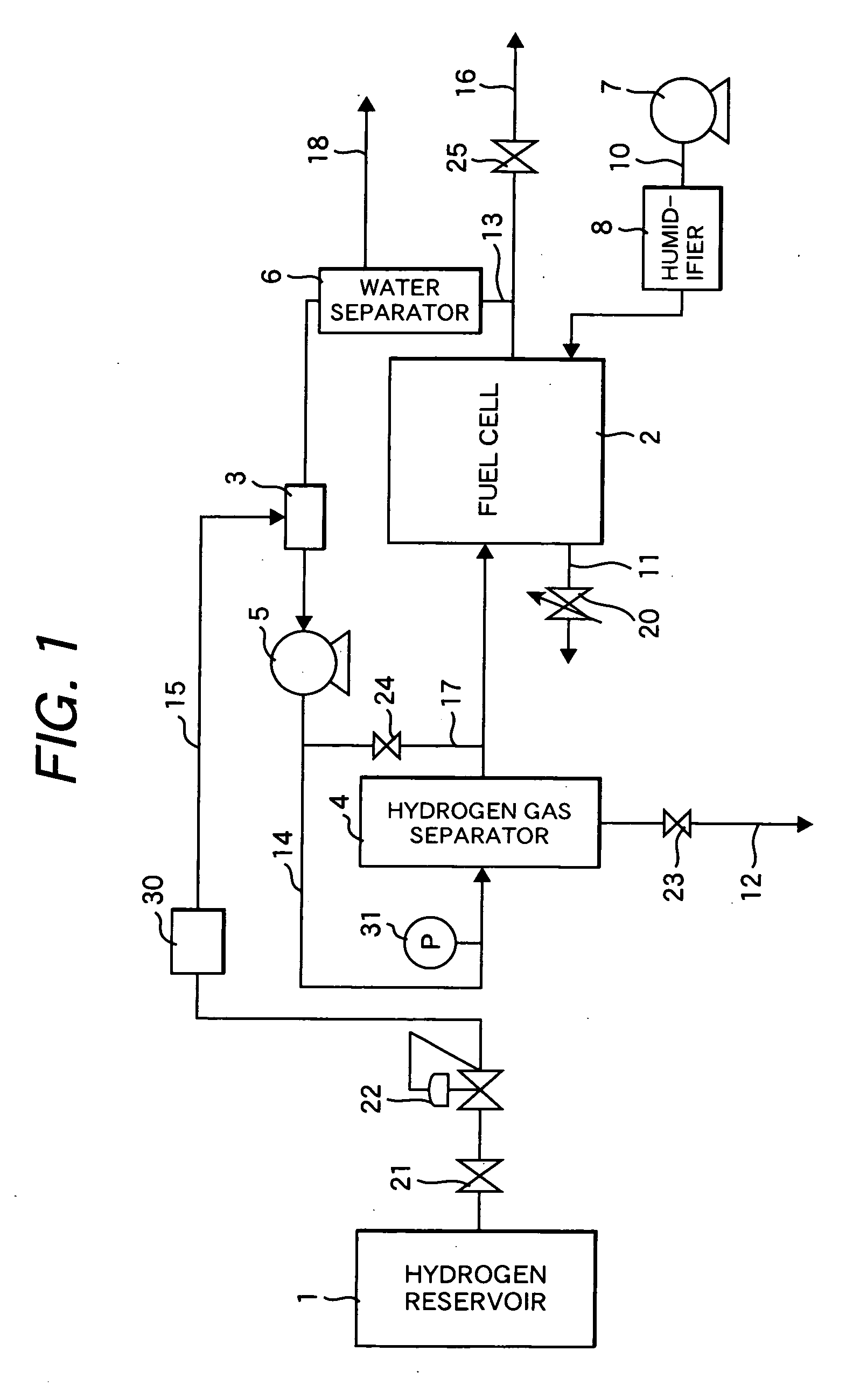
[0037]FIG. 1 is a schematic diagram illustrating the configuration of a fuel cell power generation system as an embodiment of the present invention (first embodiment). The fuel cell power generation system according to the first embodiment comprises a hydrogen reservoir 1, a fuel cell 2, a mixer 3, a hydrogen gas separator 4, and a circulation blower 5. The hydrogen reservoir 1 serves as a fuel feed unit and stores a fuel gas (anode gas) containing hydrogen gas at a high pressure. The fuel cell 2 generates power by using hydrogen gas in the fuel gas as a fuel for power generation. The mixer 3 serves to mix an exhaust gas discharged from the fuel cell 2 with the fuel gas. The hydrogen gas separator 4 separates hydrogen gas from a gas mixture discharged from the mixer 3. The circulation blower 5 pressurizes the gas mixture and conveys the pressurized gas mixture gas to the hydrogen gas separator 4.

[0038] The operation of the fuel cell power generation system illustrated in FIG. 1 wil...

embodiment 2

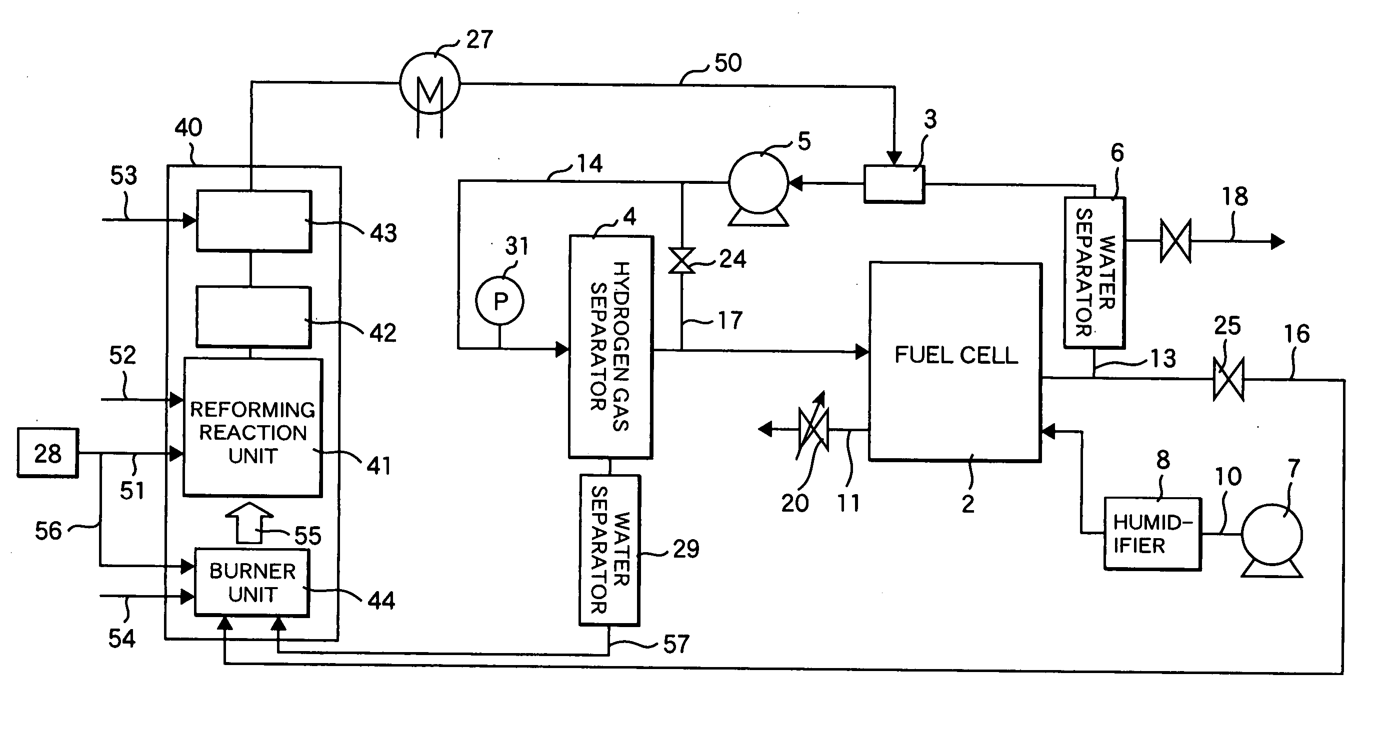
[0050]FIG. 3 illustrates another embodiment of the fuel cell power generation systems according to the present invention. The system according to the second embodiment has the same configuration and operation as the system shown in FIG. 1, except for using a reformer of a conventional external heating system as the fuel feed unit and except that the reformer herein has a different configuration. The reformer 40 comprises a reforming reaction unit 41, a carbon monoxide shift converter (CO-shift converter) 42, and a carbon monoxide-selective oxidizer 43 in this order from upstream. The reformer 40 further comprises a burner unit 44 for supplying heat necessary to the reaction to the reforming reaction unit. The reformed gas in a reformer outlet piping 50 has a hydrogen concentration of about 75% on dry basis. If the reformed gas has a high temperature, it is cooled to about 70° C. to about 90° C. in a cooler 27. The raw fuel herein is, for example, a hydrocarbon such as town gas, LPG,...

embodiment 3

[0053]FIG. 4 shows a fuel cell power generation system according to the third embodiment of the present invention. The system has a reformer 40 which comprises only the reforming reaction unit 41 and the burner unit 44 instead of the reformer in the system according to the second embodiment (FIG. 3).

[0054] The system according to the third embodiment (FIG. 4) differ from the system according to the second embodiment (FIG. 3) in that, in addition to the configuration of the reformer 40, a CO-selective oxidizer 43 is arranged between the hydrogen gas separator 4 and the fuel cell 2, and a heat exchanger 45 for the temperature control of the CO-selective oxidizer 43 is arranged upstream from the CO-selective oxidizer 43; and that another heat exchanger 46 is arranged in the reformer outlet piping 50 between the reforming reaction unit 41 and the mixer 3. The heat exchanger 46 serves to cool the reformed gas and produce steam. The raw fuel is reformed in the reforming reaction unit 41,...


PUM

PropertyMeasurementUnit
temperatureaaaaaaaaaa
concentrationaaaaaaaaaa

Abstract

A fuel cell power generation system includes a hydrogen gas separator between a fuel gas feed unit and a fuel cell, and a circulation passage and a circulation blower for conveying an anode exhaust gas to the inlet of the hydrogen gas separator. The system is so configured as to convey a mixed gas of the anode exhaust gas and the fuel gas to the hydrogen gas separator via the circulation blower, and separated hydrogen gas is fed to the fuel cell.

Description

CLAIM OF PRIORITY [0001] The present application claims priority from Japanese application serial no. 2005-228999, filed on Aug. 8, 2005, the content of which is hereby incorporated by reference into this application. FIELD OF THE INVENTION [0002] The present invention relates to fuel cell power generation systems using hydrogen gas as a fuel. BACKGROUND OF THE INVENTION [0003] Fuel cells realize energy saving, clean exhaust gas, and high energy efficiency and thereby have been received attention as possible candidates to solve environmental issues typified by air pollution caused by exhaust gases from, for examples, automobiles, and global warming caused by carbon dioxide. [0004] Fuel cell power generation systems are energy conversion systems of feeding hydrogen gas (fuel gas) and air (oxidizing gas) to a fuel electrode (anode) and an air electrode (cathode) and of causing an electrochemical reaction so as to convert chemical energy to electrical energy. The electrochemical reacti...

Claims


Application Information

Patent Timeline
Patent Type & Authority Applications(United States)
IPC IPC(8): H01M8/04H01M8/06
CPCH01M8/04097Y02E60/50H01M8/0687H01M8/0612
Inventor FUJIMURA, HIDEKAZUKOMACHIYA, MASAHIRO
Owner HITACHI LTD
Learn More