Circuit for testing inrush current

a circuit and inrush current technology, applied in the circuit field of circuits, can solve the problems of inrush current in the power supply of the computer, inability to measure the magnitude of the inrush current test, and easy damage to the power supply

Inactive Publication Date: 2007-02-08
HONG FU JIN PRECISION IND (SHENZHEN) CO LTD +1
View PDF6 Cites 2 Cited by
  • Summary
  • Abstract
  • Description
  • Claims
  • Application Information

AI Technical Summary

Benefits of technology

[0007] A circuit for testing an inrush current of a power supply includes a rectifier, a capacitor, and an ammeter. The rectifier includes input terminals adapted to connect with an AC supply, and output terminals supplying a direct voltage. The capacitor is connected in parallel to the output terminals of the rectifier. The ammeter is connected between the capacitor and the power supply. The capacitor is charged by the AC supply via the rectifier, then the capacitor supplies energy to the power supply, and the ammeter measures the magnitude of the inrush current.

Problems solved by technology

At the moment a computer is powered on, there is an inrush current in the power supply of the computer.
If the inrush current is too great, the power supply is easily damaged, so the power supply needs to be tested before being used with the computer.
But the public alternating current is unstable and variable, so the measurement of the magnitude of the tested inrush current is not reliable.
In this situation, the tester may not be sure the power supply meets performance standards.
This is a time-consuming and imprecise procedure.

Method used


Image

  • Circuit for testing inrush current
  • Circuit for testing inrush current

Examples


Embodiment Construction

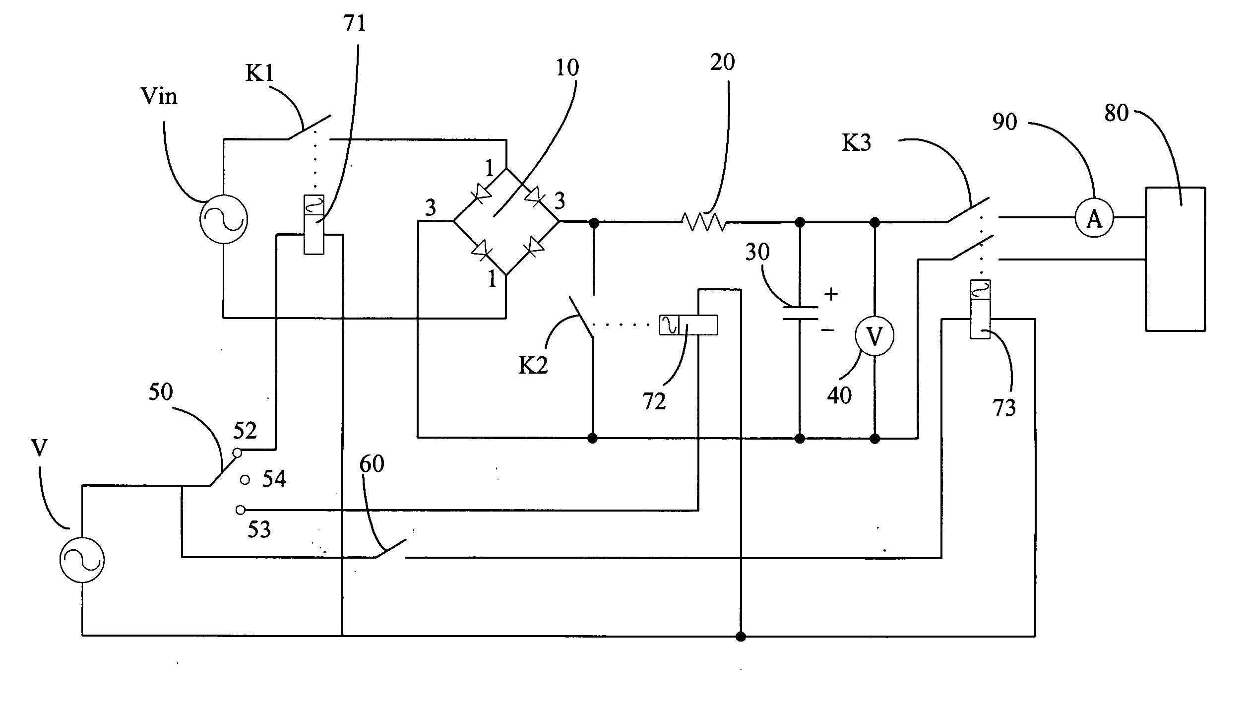
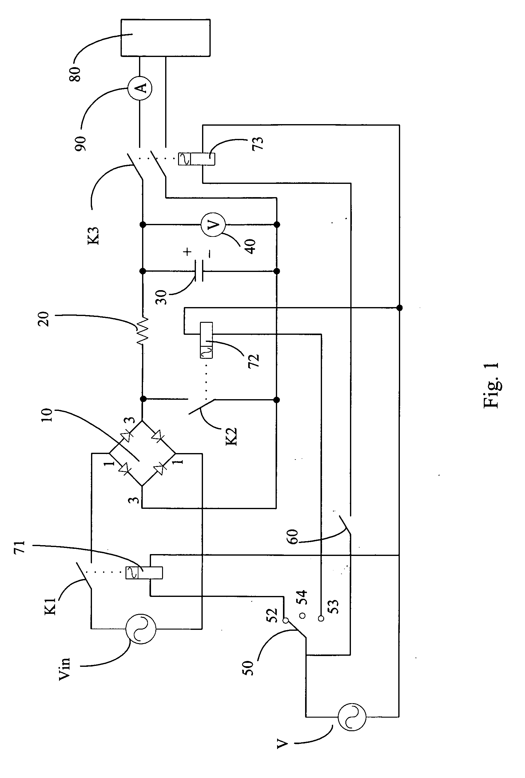
[0010] Referring to the drawing, a circuit for testing inrush current of a power supply 80 in accordance with a preferred embodiment of the present invention includes an AC (alternating current) supply Vin, a rectifier 10, a resistor 20, a capacitor 30 for providing an electrical source for the testing, and an ammeter 90.

[0011] The rectifier 10 is a known rectifier bridge, with two input terminals 1 and two output terminals 3. The AC supply Vin is coupled to the input terminals 1 via a switch K1. The capacitor 30 is connected parallel to the output terminals 3 of the rectifier 10. A voltmeter 40 is connected parallel to the capacitor 30 for measuring the magnitude of the voltage of the capacitor 30. The resistor 20 is coupled between one of the output terminals 3 of the rectifier 10 and the positive electrode of the capacitor 30. A switch K2 is coupled between one of the electrodes of the resistor 20 and the negative electrode of the capacitor 30.

[0012] A power supply 80 is connec...


PUM


Abstract

A circuit for testing an inrush current of a power supply includes a rectifier (10), a capacitor (30), and an ammeter (90). The rectifier includes input terminals (1) adapted to connect with an AC supply (Vin), and output terminals (3) adapted to supply a direct voltage. The capacitor is connected in parallel to the output terminals of the rectifier. The ammeter is connected between the capacitor and the power supply. The capacitor is charged by the AC supply via the rectifier. When the voltage of the capacitor reaches a pre-determined value, the capacitor supplies energy to the power supply, and the ammeter measures the magnitude of the inrush current.

Description

BACKGROUND OF THE INVENTION [0001] 1. Field of the Invention [0002] The present invention relates to a circuit, and more particularly to a circuit for testing inrush current. [0003] 2. General Background [0004] At the moment a computer is powered on, there is an inrush current in the power supply of the computer. If the inrush current is too great, the power supply is easily damaged, so the power supply needs to be tested before being used with the computer. [0005] The tester often uses a public alternating current source as the test electrical source. But the public alternating current is unstable and variable, so the measurement of the magnitude of the tested inrush current is not reliable. In this situation, the tester may not be sure the power supply meets performance standards. The tester must repeatedly test the power supply to be sure it can withstand the inrush current without damage. This is a time-consuming and imprecise procedure. [0006] What is needed, therefore, is a ci...

Claims


Application Information

Patent Timeline
Patent Type & Authority Applications(United States)
IPC IPC(8): H02H7/10
CPCG01R31/42
Inventor HUANG, JIAN-XIONG
Owner HONG FU JIN PRECISION IND (SHENZHEN) CO LTD
Why Eureka
Try Eureka