
Semiconductor device

a technology of semiconductor devices and semiconductor chips, applied in the field of semiconductor devices, can solve the problems of affecting the reliability of semiconductor devices, and further reducing their lifetime, so as to prevent moisture, water or salt water ingress into the inside, prevent short circuit in semiconductor chips, and increase the reliability and lifetime of semiconductor devices

Inactive Publication Date: 2007-02-08
DENSO CORP
View PDF4 Cites 0 Cited by
  • Summary
  • Abstract
  • Description
  • Claims
  • Application Information

AI Technical Summary

Benefits of technology

[0008] It is an object of the present invention to provide a semiconductor device such as a rectify element having an improved water proof capability in preventing moisture, water, or salt water ingress into a semiconductor chip fabricated in the semiconductor device in order to obtain the high reliability and long lifetime.
[0010] Further, according to the present invention, the side wall of the concave part has the tapered shape, in other words, because the inside peripheral wall of the disk section that is faced to the side wall of the concave part has the tapered shape, not perpendicular to the bottom surface of the concave part, it is possible to rapidly drain or discharge water or salt water entered into the concave part, and to prevent occurrence of short-circuit in the semiconductor chip, and thereby possible to increase the reliability and lifetime of the semiconductor device.
[0011] Still further, according to the present invention, it is preferred to fill the concave part formed in the disk section with a sealing member, with which the semiconductor chip is completely sealed. It is thereby possible to prevent moisture, water, or salt water ingress into the inside of the semiconductor chip. Furthermore, even if the sealing member is separated from the tapered side wall of the concave part, namely from the tapered inside peripheral surface of the disk section, the water ingress into the space between the sealing member and the semiconductor chip can be drained smoothly along the tapered side wall of the concave part to the outside. Therefore it is possible to prevent any moisture, water, or salt water ingress into the semiconductor chip.
[0012] Furthermore, according to the present invention, it is preferred to form a circular groove or a circular convex part at the bottom surface of the concave part, namely the inside upper surface of the disk section around the outer peripheral section of the semiconductor chip. It is thereby difficult to enter moisture, water, or salt water ingress into the semiconductor chip through the side wall of the concave part. As a result, it is possible to further prevent any moisture, water, or salt water ingress into the semiconductor chip.

Problems solved by technology

Thus, the semiconductor device involves various drawbacks, for example, the semiconductor chip falls in short circuit by water, moisture, or salt water ingress, and its reliability deteriorates and its lifetime is further decreased, or the semiconductor device thereby falls in failure.

Method used


Image

  • Semiconductor device
  • Semiconductor device
  • Semiconductor device

Examples


embodiment

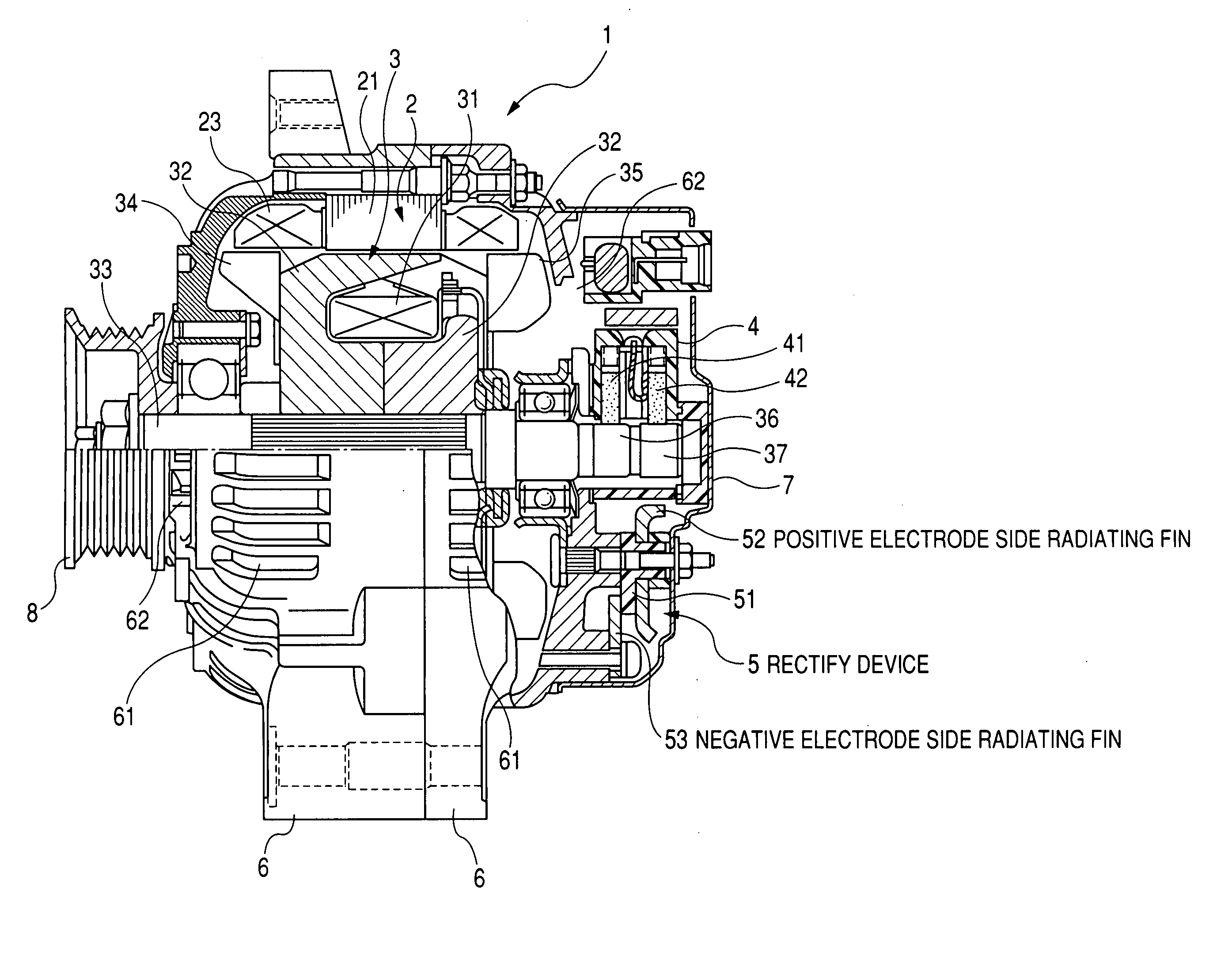
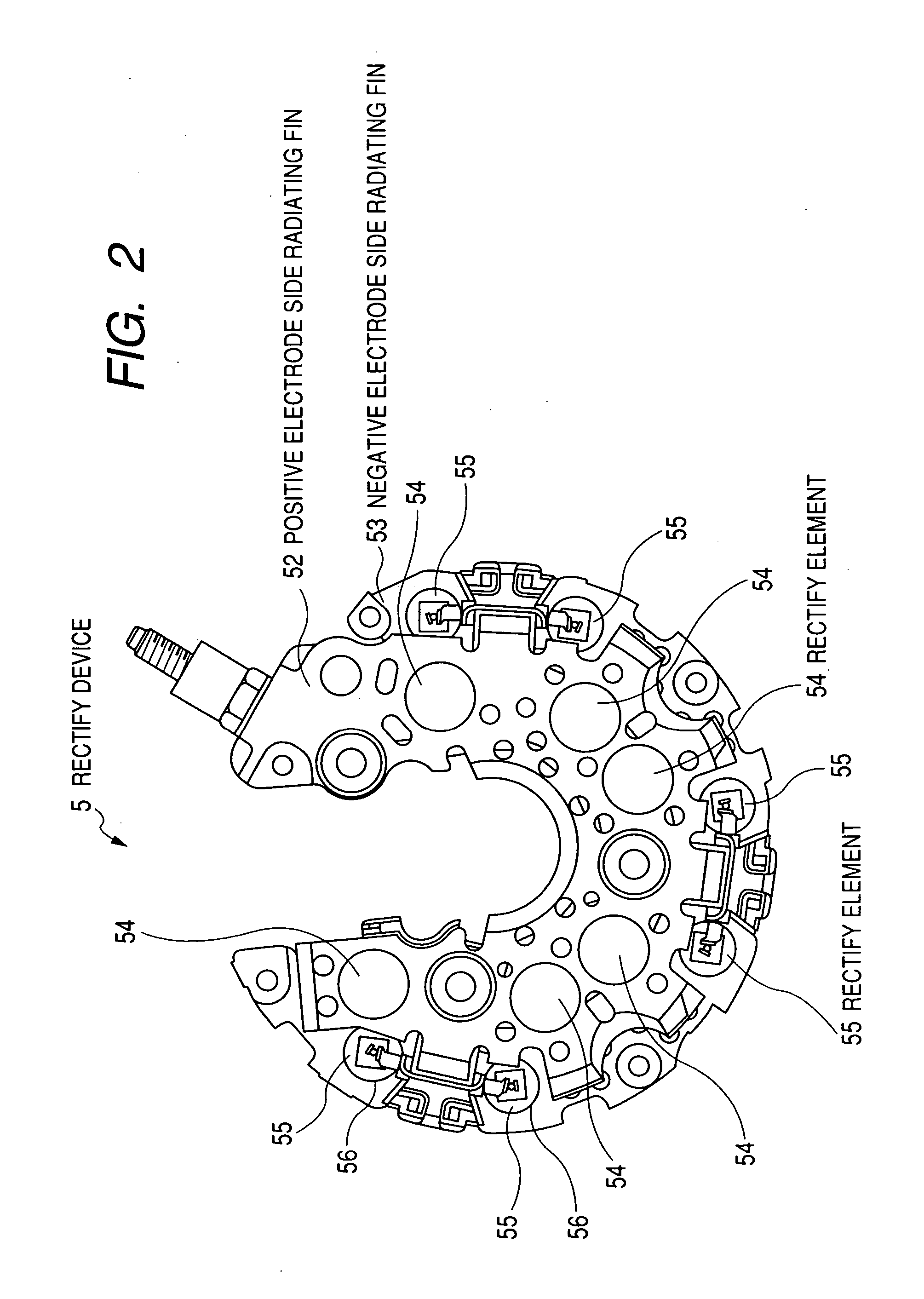
[0020] A description will be given of a configuration of a semiconductor device as a rectify element according to an embodiment of the present invention to be applied to a vehicle alternator with reference to FIG. 1 to FIG. 5.

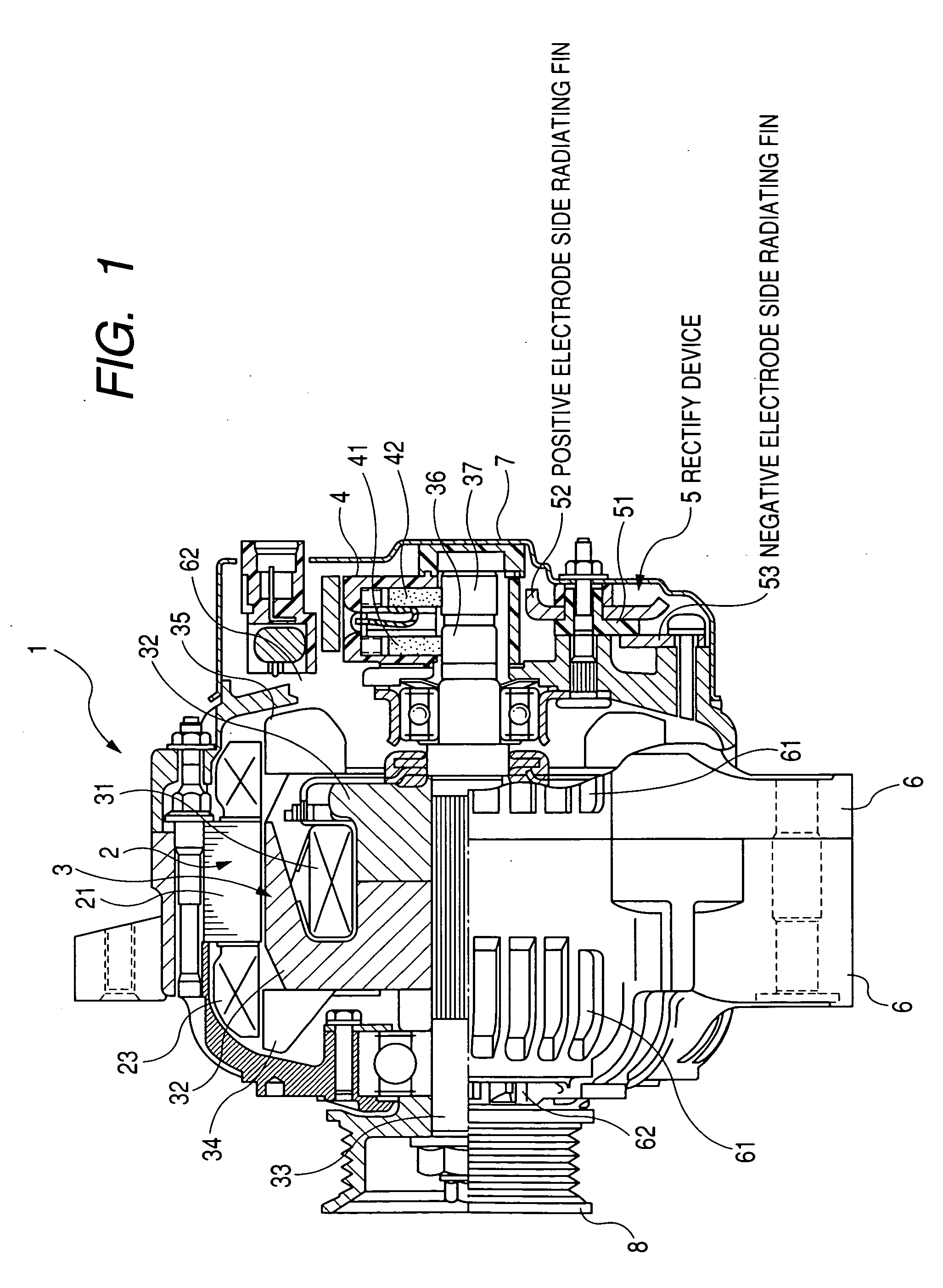
[0021]FIG. 1 is a sectional view showing the entire configuration of the vehicle alternator equipped with the rectify device to be mounted on a vehicle according to the embodiment of the present invention.

[0022] As shown in FIG. 1, the vehicle alternator 1 has a stator 2, a rotor 3, a brush device 4, a rectify device 5, a frame 6 made of several parts, a pulley 8, and the like.

[0023] The stator 2 consists of a stator core 21 and three phase stator windings 23 wound on a plurality of slots that are formed in the stator core 21 at a specified interval to each other.

[0024] The rotor 3 has an insulating bobbin, a cylindrical field coil, and a pair of pole cores 32. The cylindrical field coil is made of copper wire treated with electric insulation wound around t...


PUM


Abstract

A rectify element as a semiconductor device has a disk section, a first solder part, a buffer plate, a second solder part, a semiconductor chip, and a lead, and a sealing member with which the semiconductor chip is sealed. A cylindrical concave part is formed at one end surface of the disk section. A side wall of the cylindrical concave part faced to an inner peripheral wall at the upper surface of the disk section has a sloped shape of an angle of more than 90° to a contact surface of the upper surface of the disk section on which the semiconductor chip is placed.

Description

CROSS-REFERENCE TO RELATED APPLICATION [0001] This application is related to and claims priority from Japanese Patent Application No. 2005-226065 filed on Aug. 4, 2005, the contents of which are hereby incorporated by reference. BACKGROUND OF THE INVENTION [0002] 1. Field of the invention [0003] The present invention generally relates to a semiconductor device as a rectify element incorporated in a rectify device to be applied to a vehicle alternator mounted on a vehicle such as a passenger car and a truck. [0004] 2. Description of the Related Art [0005] A vehicle alternator is driven by the engine power generated by and transmitted from an internal combustion engine mounted on a vehicle in order to generate electric power. The vehicle alternator supplies the generated electric power to a battery, and the battery charges the electric power therein. The vehicle alternator also supplies the generated electric power to various kinds of electric devices and loads mounted on the vehicle ...

Claims


Application Information

Patent Timeline
Patent Type & Authority Applications(United States)
IPC IPC(8): H01L23/495
CPCH01L23/24H01L23/492H01L24/33H01L2924/01033H01L2924/01082H01L2924/01006H01L2924/01029H01L2924/181H01L2924/00012
Inventor KATAOKA, SHIGEKAZU
Owner DENSO CORP
Learn More