Physical quantity sensor and manufacturing method therefor

a technology of physical quantity sensor and manufacturing method, which is applied in the direction of acceleration measurement using interia force, microstructural device, instruments, etc., can solve the problems of difficult further reducing the dimensions increasing the thickness of the physical quantity sensor (lying in the z-axis direction), and being susceptible to damage, so as to reduce the size speed up the production of the physical quantity sensor. , the effect of easy inclination

Inactive Publication Date: 2007-02-08
YAMAHA CORP
View PDF9 Cites 3 Cited by
  • Summary
  • Abstract
  • Description
  • Claims
  • Application Information

AI Technical Summary

Benefits of technology

[0026] It is an object of the present invention to provide a physical quantity sensor and a manufacturing method therefor, in which the physical quantity sensor is downsized with a simple structure.
[0027] It is another object of the present invention to provide a manufacturing method for a physical quantity sensor without using metal molds, which are used to hold a lead frame therebetween. Even though metal molds are used in manufacturing, the present invention makes it possible to improve the durability of metal molds. In addition, the present invention makes it possible to quickly and easily manufacture physical quantity sensors.
[0028] It is a further object of the present invention to provide a manufacturing method for a physical quantity sensor, which can be reduced in size and which can be smoothly produced with a reduced cost.

Problems solved by technology

This causes a bottleneck making it difficult further reduce dimensions of the physical quantity sensor 100.
For example, one type of known magnetic sensor presently sold on the market is designed such that stages facilitating physical quantity sensor chips are not necessarily inclined with respect to prescribed bases.
However, the aforementioned magnetic sensor is basically designed such that the second magnetic sensor chip vertically stands on the surface of the substrate; hence, it is disadvantageous in that the thickness thereof (lying in the Z-axis direction) must be increased.
In the aforementioned manufacturing method, the projections are subjected to pressing using a pair of metal molds, which are therefore likely to be damaged.
In addition, it may require a troublesome work to precisely incline the stages by pressing.
As the stages of the lead frame are subjected to inclination using the upper and lower molds by way of the projections, which project from the stages, the physical quantity sensor has a drawback in that the overall size of the package encapsulating the lead frame and physical quantity sensor chips is increased due to the provision of the projections.

Method used


Image

  • Physical quantity sensor and manufacturing method therefor
  • Physical quantity sensor and manufacturing method therefor
  • Physical quantity sensor and manufacturing method therefor

Examples


first embodiment

1. First Embodiment

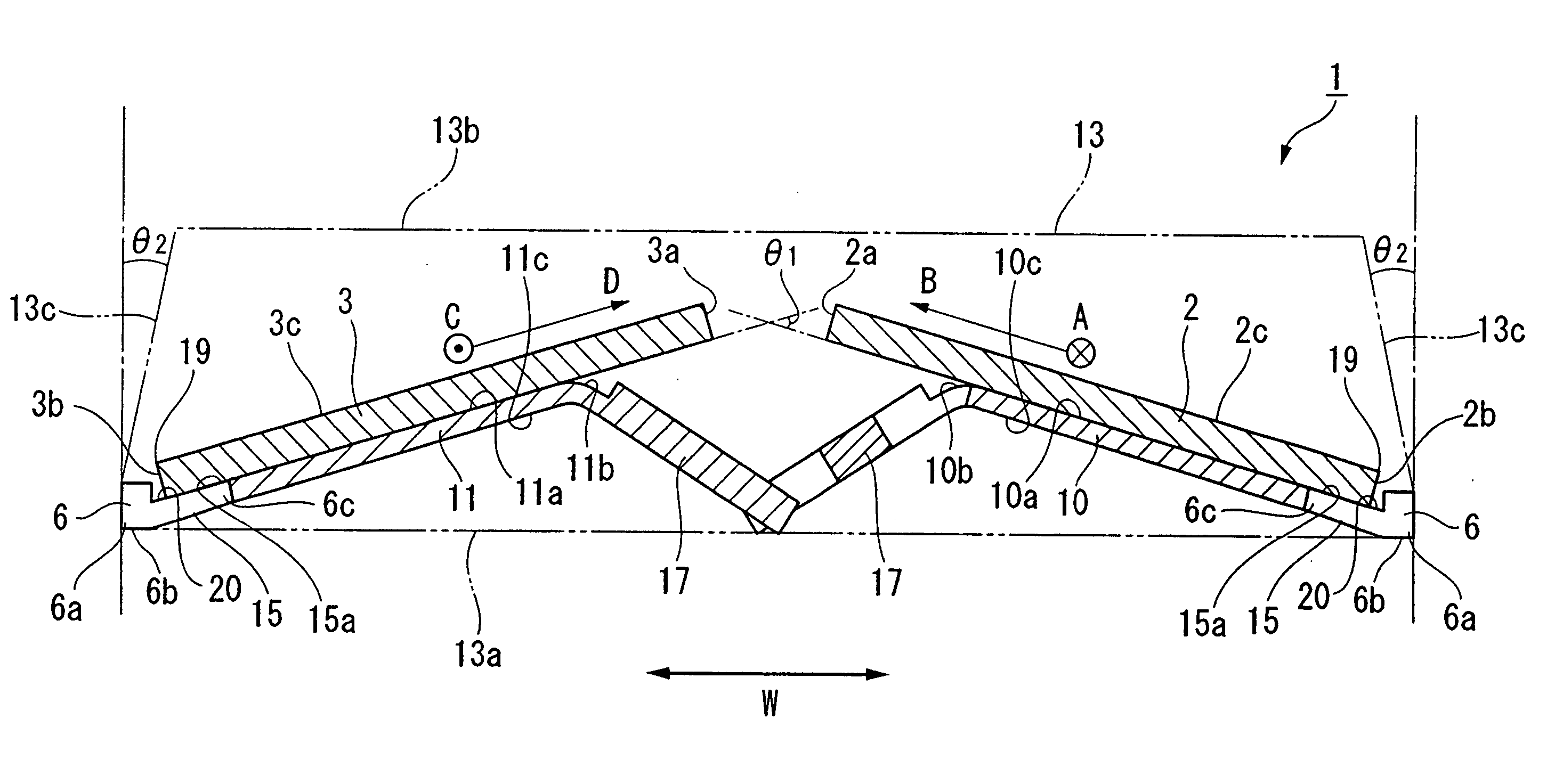
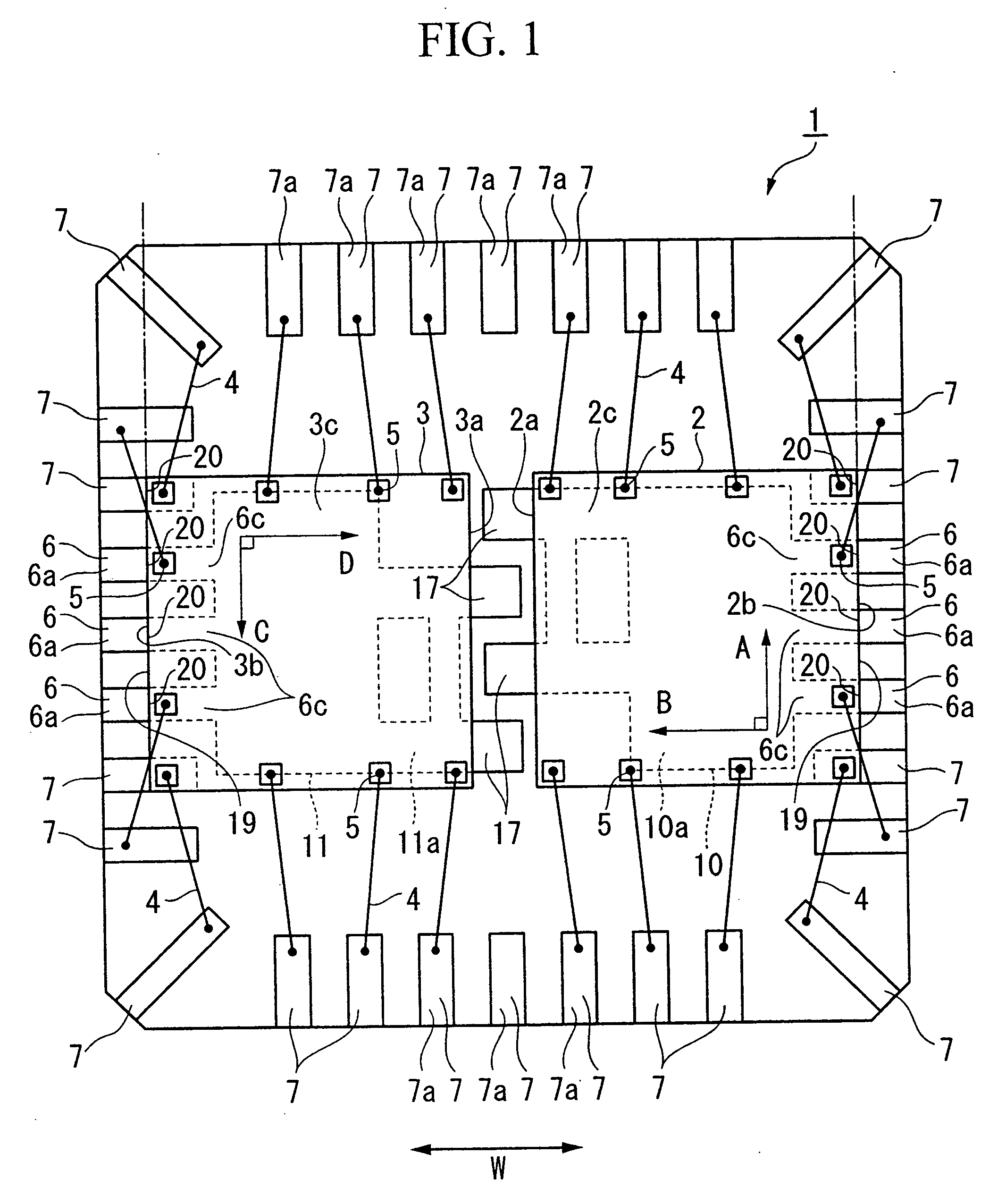
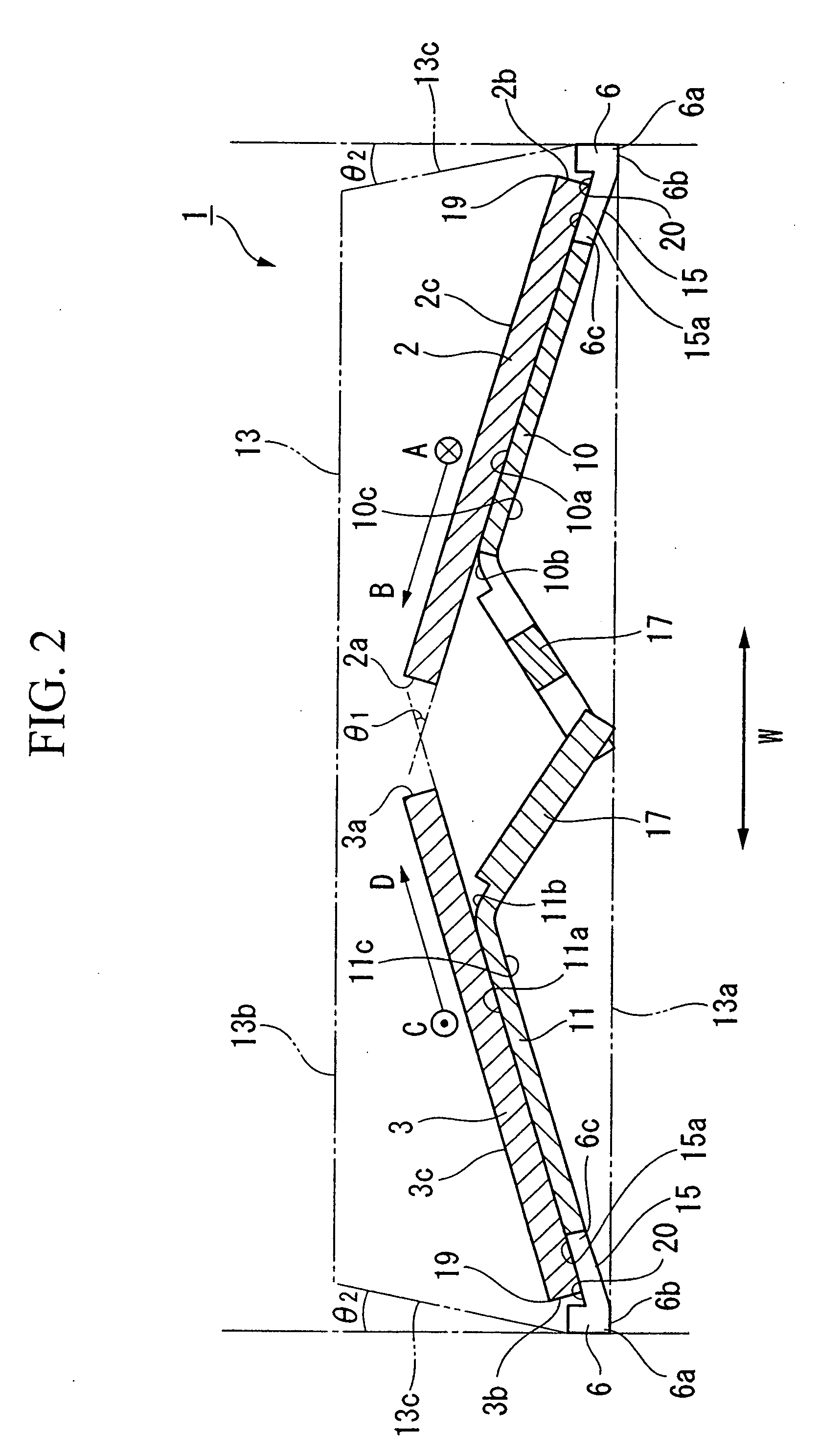
[0086]FIGS. 1 and 2 show a magnetic sensor 1 in accordance with a first embodiment of the present invention.

[0087] The magnetic sensor 1 is designed to measure the magnitude and direction of an external magnetic field, wherein it includes an exterior mold package 13, which is molded using a resin, as well as a first magnetic sensor chip 2 and a second magnetic sensor chip 3, both of which are incorporated in the exterior mold package 13.

[0088] Each of the magnetic sensor chips 2 and 3 has a rectangular plate-like shape in plan view, wherein they are respectively mounted on a first stage 10 and a second stage 11, which adjoin each other in a length direction W of the magnetic sensor 1. The magnetic sensor chips 2 and 3 are respectively inclined with respect to a bottom 13a of the exterior mold package 13. Specifically, the stages 10 and 11 are respectively inclined with respect to the bottom 13a by way of projections 17 therefor; hence, inner ends 2a and 3a of th...

fourth modification

(4) Fourth Modification

[0139]FIG. 15 shows a fourth modification of the present embodiment, wherein parts identical to those shown in FIGS. 1 to 7 are designated by the same reference numerals; hence, the detailed description thereof will be omitted.

[0140] The fourth modification is basically similar to the present embodiment, wherein the following description will be given with respect to differences therebetween.

[0141] In short, a magnetic sensor 1 according to the fourth modification is characterized in that the side surfaces 13c of the exterior mold package 13 are not inclined; that is, the angle θ2 is set to zero.

[0142] Similar to the present embodiment, a manufacturing method of the fourth modification includes a bonding step, a connection step, a fixing step, and a molding step. In addition, the fourth modification additionally introduces a dicing step in which the lead frame 22 and the exterior mold package 13 are subjected to dicing such that the inclination angle of the...

fifth modification

(5) Fifth Modification

[0146]FIG. 16 shows a fifth modification of the present embodiment, wherein parts identical to those shown in FIG. 15 are designated by the same reference numerals; hence, the detailed description thereof will be omitted.

[0147] The fifth modification is basically similar to the fourth modification, wherein the following description will be given with respect to difference therebetween.

[0148] The fifth modification does not use the foregoing dicing step but performs cutting on a lead frame 22, which is fixed in metal molds, in accordance with a through-gate method.

[0149] In the through-gate method, metal molds provide cavities that are used to form a plurality of chips and that are connected via runner gates 27. Cavities close to pods are sequentially filled with a resin, so that a resin introduced into one cavity is supplied to a next cavity via the runner gate 27. After completion of the molding step, a cutting metal mold is used to cut the lead frame 22 in...


PUM


Abstract

A physical quantity sensor includes a pair of physical quantity sensor chips that are inclined with respect to the bottom of an exterior mold package whose side surfaces are each inclined in a thickness direction by an angle ranging from 0° to 5° and are formed in proximity to the outer ends of the physical quantity sensor chips. It is possible to realize the inclination of stages without using molds, wherein absorption devices are used to absorb prescribed portions related to stages, which rotate about axial lines and are thus inclined with respect to a prescribed base. In manufacturing, a thin metal plate having a plurality of lead frames is placed on a base delimited by a clamp; then, intersecting points of intermediate portions formed between the lead frames are subjected to pressing so as to realize the inclination of stages.

Description

CROSS REFERENCE TO RELATED APPLICATIONS [0001] This application is a Divisional of application Ser. No. 11 / 244,194, filed Oct. 6, 2005, entitled PHYSICAL QUANTITY SENSOR AND MANUFACTURING METHOD THEREFOR, the entire disclosure of which is incorporated herein by reference.BACKGROUND OF THE INVENTION [0002] 1. Field of the Invention [0003] The present invention relates to physical quantity sensors that measure bearings and directions regarding physical quantities such as magnetism and gravitation. The present invention also relates to manufacturing methods of physical quantity sensors. [0004] This application claims priorities on Japanese Patent Applications Nos. 2004-296371, 2005-45299, 2005-89629, and 2005-94388, the contents of which are incorporated herein by reference. [0005] 2. Description of the Related Art [0006] Recently, sensing technologies regarding measurement of bearings and directions in a three-dimensional space have been developed to provide various types of physical ...

Claims


Application Information

Patent Timeline
Patent Type & Authority Applications(United States)
IPC IPC(8): G01P1/02
CPCB81B7/0077B81B2201/0235B81B2201/025H01L24/97H01L2224/48247H01L2224/49171H01L2924/00H01L2924/181H01L2224/05554H01L2224/48091H01L2224/97H01L2924/00012H01L2924/00014
Inventor SHIRASAKA, KENICHISAITOH, HIROSHI
Owner YAMAHA CORP
Why Eureka
Try Eureka