Pest control system

a control system and pest technology, applied in the field of pest control systems, can solve the problems of unfavorable environmental protection, unfavorable human health, and certain risks to the environment, and achieve the effects of preserving structural integrity of the building or enclosure, and reducing the impact of adverse effects

Inactive Publication Date: 2007-02-01
ABARAW MIMOUN
View PDF60 Cites 19 Cited by
  • Summary
  • Abstract
  • Description
  • Claims
  • Application Information

AI Technical Summary

Benefits of technology

[0010] A ramp-up rate of up to about 10° F. per hour is most desirable, though higher temperature ramp-up rates are contemplated by the present invention as being useful in certain applications. Typically, an upper limit to temperature ramp-up rates is desired in order to preserve structural integrity of the building or enclosure. Rates substantially in excess of about 10° F. per hour may result in adverse effects to the structure and its overall integrity. By controlling the ramp-up rate within a safe range, therefore, it is possible to both trap and kill the pests in hard-to-reach places, as well as reducing the impact of adverse affects due to induced thermal stresses.
[0017] It is yet a further object of the present invention to provide an effective time-expedient technique for pest extermination utilizing thermal treatment for undertaking and completing the extermination operation.

Problems solved by technology

These techniques involve certain risks to personnel, as well as to the environment, and hence are not readily undertaken without necessary precautions.
Some are environmentally unfriendly.

Method used


Image

  • Pest control system
  • Pest control system

Examples


Embodiment Construction

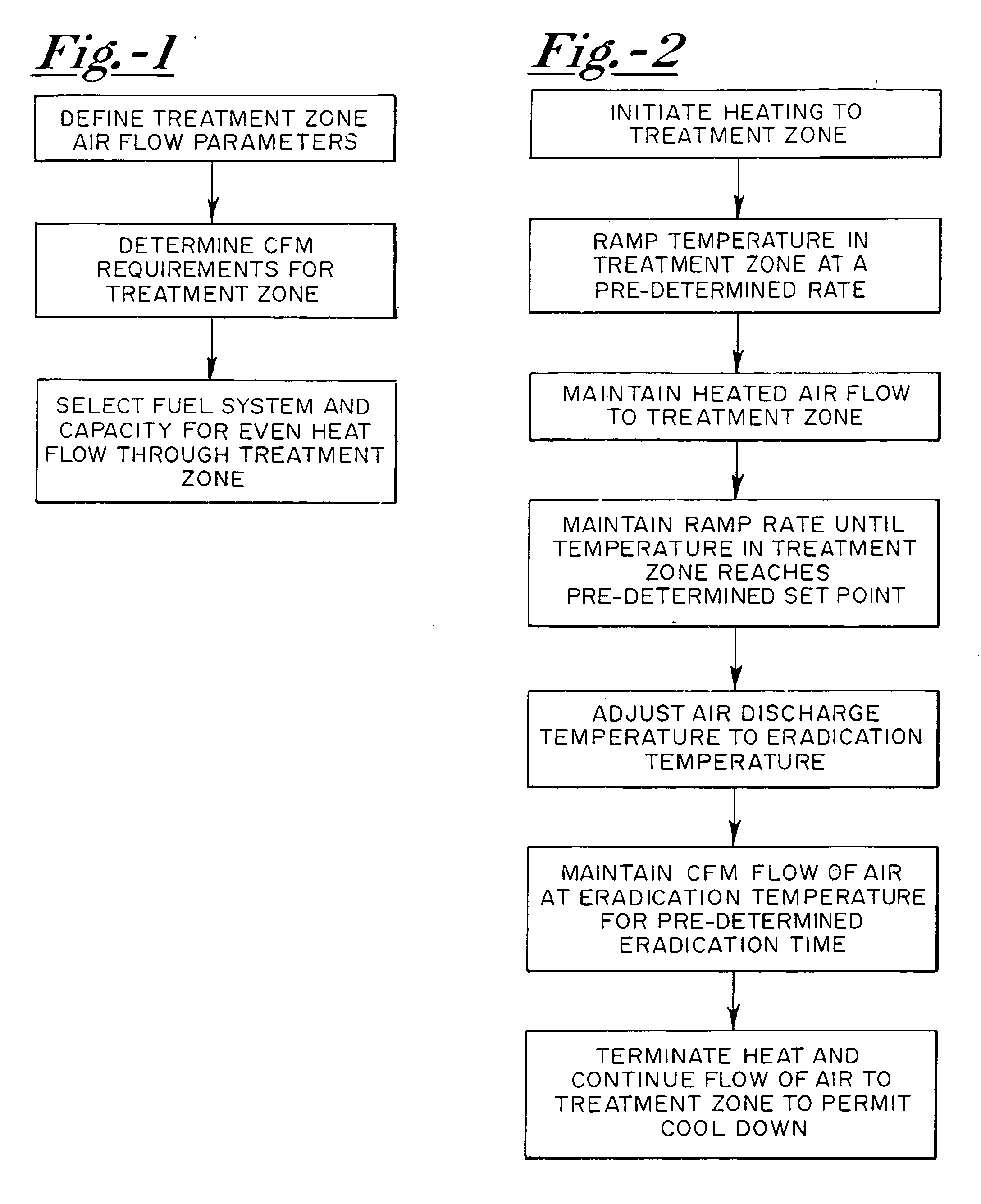
[0021] In accordance with the preferred embodiment of the present invention, the thermal treatment of a zone for extermination of pests is undertaken as follows. It is believed that the recitation of steps set forth below will enable those of skill in the art to readily and effectively practice the technique.

Treatment Zone Defined

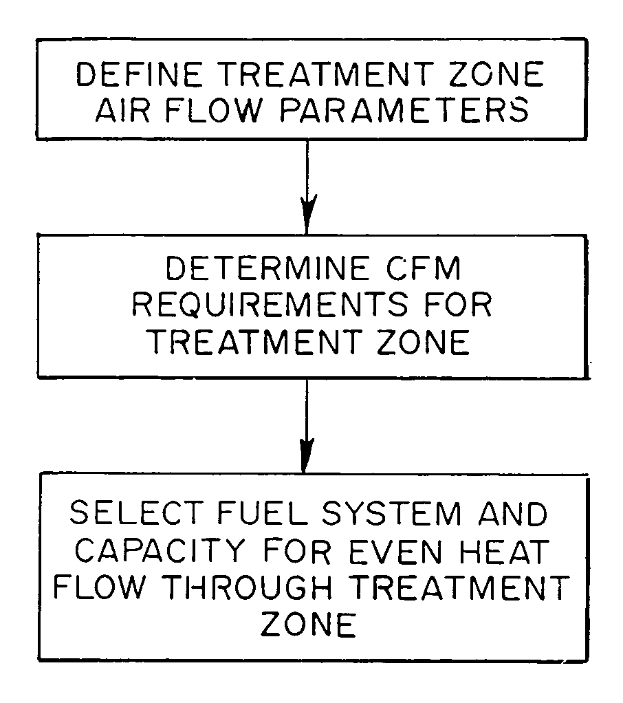
[0022] The dimensions, type of structure, as well as area of structure for heat treatment is analyzed and determined. This determination enables the technician to establish some basic guidelines for the equipment necessary to effectively handle the procedure. Accordingly, the nature of the heat source and fuel supply is determined, along with the equipment installation factors.

[0023] The step of defining treatment zone air flow is then undertaken with respect to heat movement, air distribution, placement of the equipment being utilized, and desired locations for heated air inlet and discharge. This step may generally be characterized as the determination...


PUM

PropertyMeasurementUnit
temperatureaaaaaaaaaa
timeaaaaaaaaaa

Abstract

A method of pest control which includes heating the affected area to a temperature which is lethal for the pests being exterminated, and maintaining this elevated temperature in the zone for a predetermined period of time. The treatment is undertaken after determining the air flow parameters for the treatment zone, so as to be able to determine the CFM requirements for achieving a requisite air flow rate of between 0.5 and 70 air changes per hour in the treatment zone. Heated air is introduced to the treatment zone at the requisite air flow rate and at an initial temperature of at least about 240° F., with the temperature in the treatment zone being elevated at a predetermined rate until the air temperature reaches a predetermined set point. Once the predetermined set point temperature is reached within the treatment zone, the introduced heated air is adjusted to an eradication temperature and maintained in such a condition for a predetermined period of time sufficient to eradicate respective pests within the treatment zone.

Description

FIELD OF THE INVENTION [0001] The present invention relates generally to a method for exterminating pests by thermal treatment of enclosed pest-occupying zones, wherein the zone is treated with heated air under controlled conditions for a period of time sufficient to achieve extermination of the pests. The term “pests” is intended to refer generally to creatures such as insects, mammals, reptiles, and the like, but may also include some other undesirable but non-toxic forms of matter such as certain types of bacteria, molds, and viruses. BACKGROUND OF THE INVENTION [0002] In the past, various techniques have been employed to exterminate pests, including the introduction of toxic or lethal gases, such as those used in typical fumigation techniques including methyl bromide, phosphine, or the like. These techniques involve certain risks to personnel, as well as to the environment, and hence are not readily undertaken without necessary precautions. Some are environmentally unfriendly. O...

Claims


Application Information

Patent Timeline
Patent Type & Authority Applications(United States)
IPC IPC(8): C21D1/74
CPCA01M1/2094A61L2/06A01M19/00A01M1/24
Inventor ABARAW, MIMOUN
Owner ABARAW MIMOUN
Why Eureka
Try Eureka