Flat panel display mounting apparatus and system

Inactive Publication Date: 2007-02-01
FEDEWA DALE
View PDF14 Cites 69 Cited by
  • Summary
  • Abstract
  • Description
  • Claims
  • Application Information

AI Technical Summary

Benefits of technology

[0012] The present invention has been developed in response to the present state of the art, and in response to the problems and needs in the art that have not yet been fully solved by currently available display mounting apparatuses and systems. Inparticular, the invention addresses the adjustment capabilities of display mounting systems while minimizing problems of cost, complexity, and size.
[0016] In one embodiment, the attachment bracket comprises a tilt bracket, with the first attachment point being positioned on the tilt bracket. The tilt bracket is configured to rotate around the attachment point of the arms, allowing for tilting movement of the display.
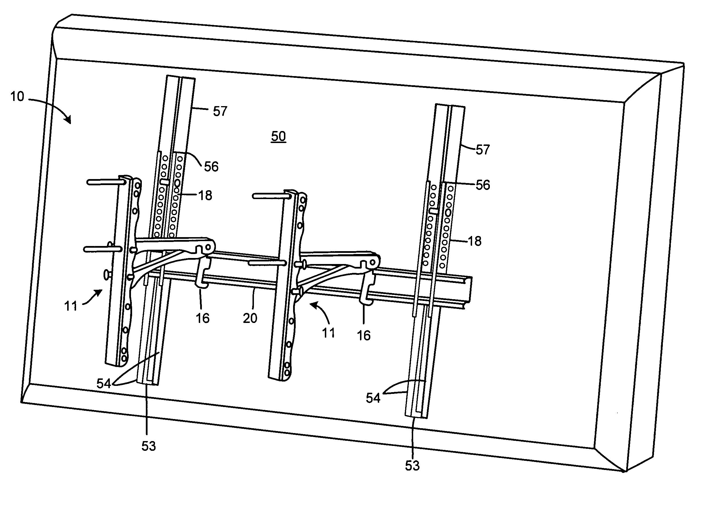
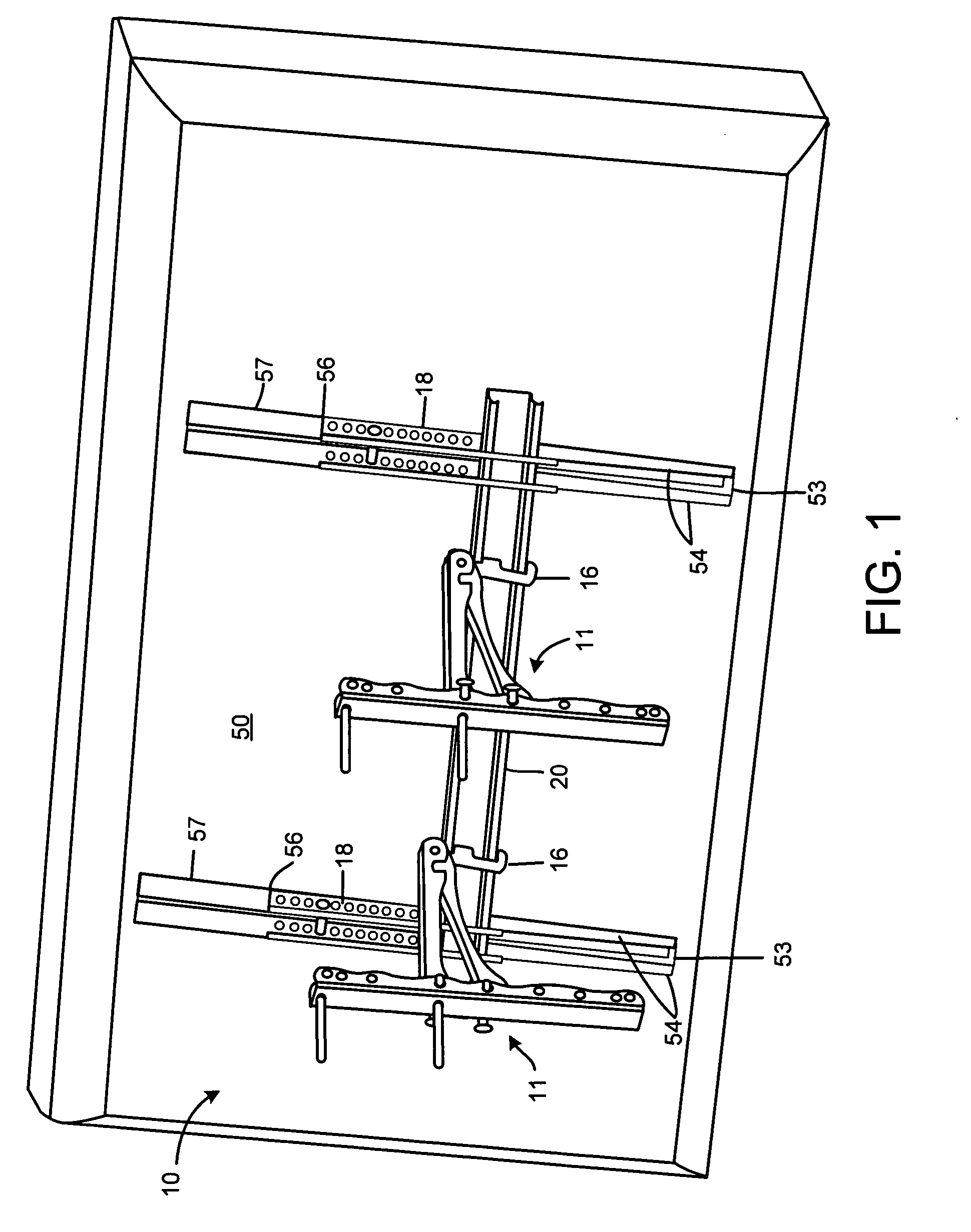
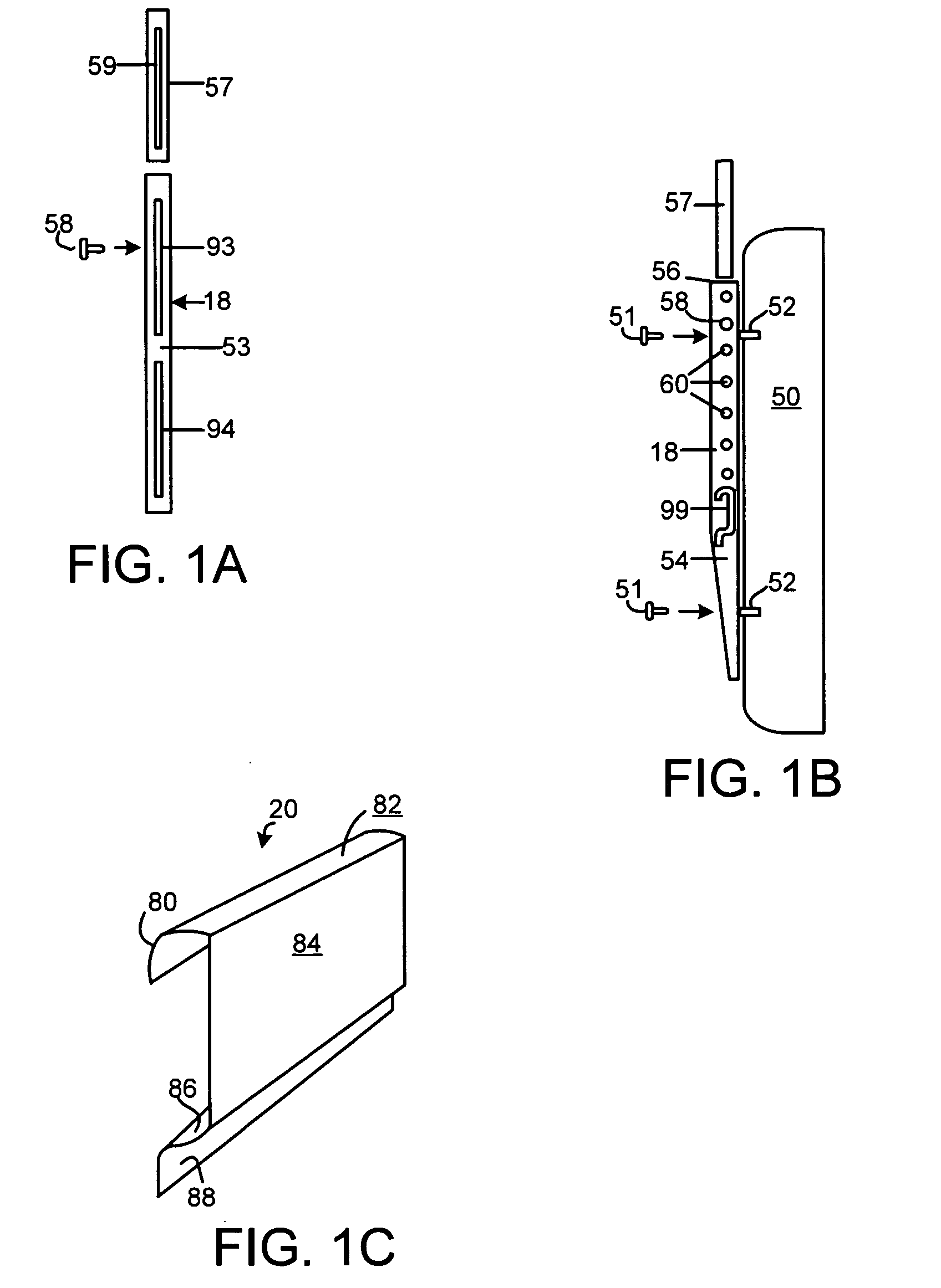
[0018] The vertical attachment members contain a plurality of attachment points whereby the display can be attached, allowing for a plurality of positions of the display relative to the vertical attachment member. Extension members can be provided to extend the length of the vertical attachment members and provide further attachment points.
[0019] The mounting bracket, first arm, second arm, and tilt bracket collectively constitute a first mounting assembly. The apparatus further comprises a second mounting assembly of similar construction to the first, the second mounting bracket being adapted for attachment to the mounting surface horizontally spaced from the location at which the first mounting bracket is attached. The second tilt bracket is configured for attachment to the cross member horizontally spaced from the attachment of the first tilt bracket, enabling the display to be panned by positioning the first tilt bracket and mounting bracket closer to each other than the second tilt bracket and mounting bracket.

Problems solved by technology

Given their design, however, such systems are often limited in their capabilities, and systems that allow for wider adjustment of the display are generally expensive, heavy, and large, limiting the surfaces on which a flat-panel display can be mounted.
Generally, the more numerous the ways of adjusting position and orientation in mounting systems, the larger, more expensive, and more complex the mounting system becomes.
Some existing mounting systems take up 1,500 cubic inches of space, limiting the locations in which they may be placed.
The complex nature of many mounting systems also detracts from the sleek aesthetic appeal of the flat-panel display, which is one of the primary reasons consumers purchase such displays in the first place.
Many mounting systems are further limited in that they are unable to accommodate more than one or a few of the large variety of screens offered by different manufacturers—and often the same manufacturer—which can vary in weight, height, depth, breadth, delicacy, and method of mounting.

Method used


Image

  • Flat panel display mounting apparatus and system
  • Flat panel display mounting apparatus and system
  • Flat panel display mounting apparatus and system

Examples


Embodiment Construction

[0037] It will be understood that the components of the present invention, as generally described and illustrated in the figures herein, may be arranged and designed in a wide variety of different configurations. Thus, the following, more detailed, description of the embodiments of the apparatus, system, and method of the present invention is not intended to limit the scope of the invention as claimed, but is merely representative of selected embodiments.

[0038] The illustrated embodiments of the invention will be best understood by reference to the drawings, wherein like parts are designated by like numerals throughout. Those of ordinary skill in the art will appreciate that various modifications to the devices, systems, and processes may readily be made without departing from the essential characteristics of the invention. Thus, the following description is intended only by way of example, illustrating certain selected embodiments of devices, systems, and processes that are consis...


PUM


Abstract

A display mounting apparatus and system can be adjusted in differing ways, separately or in combination, including tilting, panning, and translational movement vertically, horizontally, and perpendicular to the wall or other mounting surface. The apparatus comprises two mounting assemblies spaced at variable distances from each other, each assembly comprising a mounting bracket, a scissors mounting assembly attached to the mounting bracket at a plurality of points, and a tilt bracket to which the scissors assembly attaches at one point, the tilt bracket being configured to swivel around the scissors assembly attachment point. Each tilt bracket can be moved perpendicular to the wall by varying the attachment locations of the scissors assembly to the mounting bracket. A horizontal cross member is slidably attached to the tilt brackets, and vertical attachment members configured for attachment to the display at a plurality of points are slidably attached to the horizontal cross member.

Description

BACKGROUND OF THE INVENTION [0001] 1. Field of the Invention [0002] This invention relates to mounting systems, and more particularly to a flat-panel display mounting apparatus, which enables the display to be attached to a mounting surface and positioned at an optimum viewing location and angle. [0003] 2. Description of the Related Art [0004] The popularity of electronic flat-panel displays, such as for televisions and computers, has greatly increased in recent years as such displays have become increasingly available and inexpensive. Currently manufactured and marketed displays come in a variety of different sizes and types, including liquid-crystal, light-emitting-diode, and plasma screens. Given that they are thinner than traditional cathode-ray or projection displays, these displays may be positioned or mounted in a commensurately large variety of places and ways; particularly, as is becoming increasingly popular, on a wall or similar mounting surface. Ways of mounting the disp...

Claims


Application Information

Patent Timeline
IPC IPC(8): F16M11/00
CPCF16M11/10F16M13/02F16M11/24
Inventor FEDEWA, DALE
Owner FEDEWA DALE
Why Eureka
Try Eureka