
Gas turbine blade or vane and platform element for a gas turbine blade or vane ring of a gas turbine, supporting structure for securing gas turbine blades or vanes arranged in a ring, gas turbine blade or vane ring and the use of a gas turbine blade or vane ring

Inactive Publication Date: 2007-01-25
SIEMENS AG
View PDF9 Cites 63 Cited by
  • Summary
  • Abstract
  • Description
  • Claims
  • Application Information

AI Technical Summary

Benefits of technology

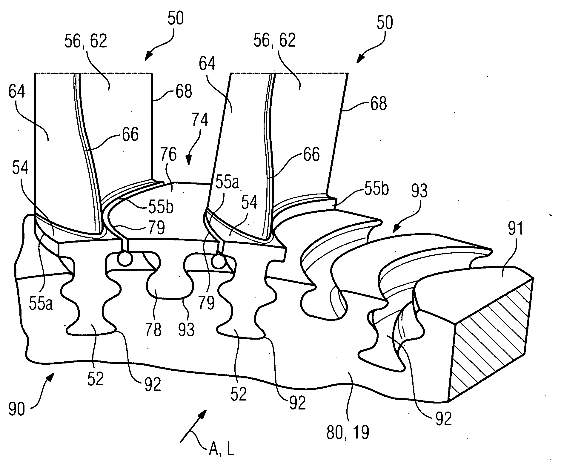
[0011] The approximately constant platform width allows significantly simpler and more efficient cooling of the platform. During use in a gas turbine, this leads to a more uniform temperature distribution, which in turn lengthens the service life of the gas turbine, on account of the reduced material stresses.
[0017] It is particularly advantageous for a suction-side or pressure-side platform protuberance, the platform width of which is approximately constant over 30% of its length running in the longitudinal direction, to project from the suction-side profile wall to the suction-side platform longitudinal edge and / or from the pressure-side profile wall to the pressure-side platform longitudinal edge. On account of the approximately constant platform width, the transition from platform to blade profile is exposed to more uniform thermal and mechanical stresses in operation. A platform configured in this manner can be cooled particularly well and uniformly and avoids platform protuberances which are uneven on account of having significantly different widths along the blade profile. Moreover, the fatigue strength can be increased, on account of the stresses now being more even.
[0018] A particularly small platform can be achieved if the suction-side and / or pressure-side platform protuberance is designed as a platform stub with a relatively short platform width. In this case, the gas turbine blade or vane is almost platform-free, which significantly simplifies its structural design. This simplification leads to a reduction in costs when designing the gas turbine blade or vane and producing it. Moreover, the material stresses which occur in the transition region between blade profile and platform and which are responsible for the premature fatigue are eliminated.
[0019] It is preferable for the gas turbine blade or vane to be designed as a gas turbine rotor blade, the blade root of which is designed in dovetail, hammer or fir tree form in cross section. Moreover, the preferably cast gas turbine blade or vane is coolable.
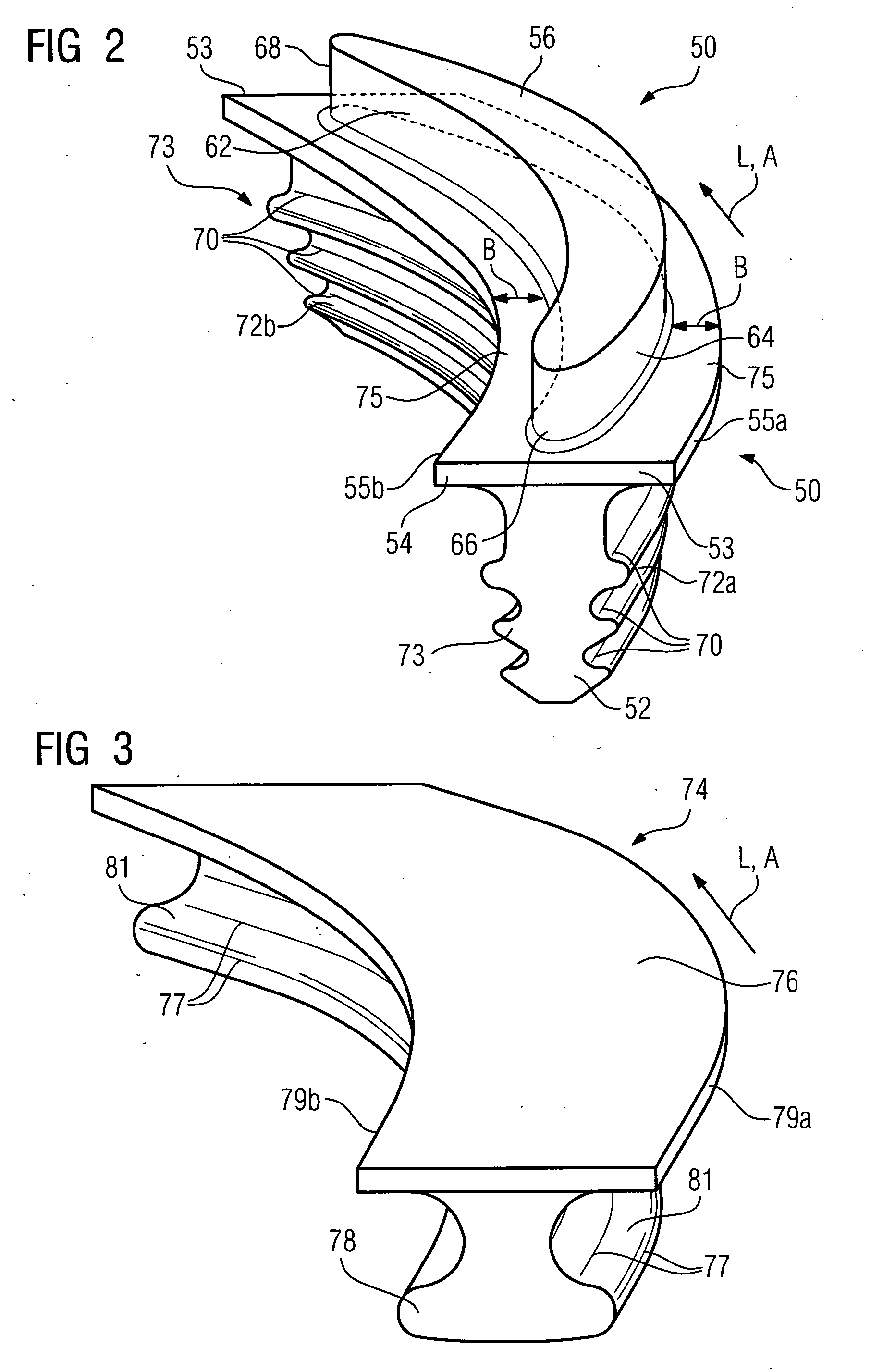
[0022] To provide a particularly inexpensive and / or temperature- and corrosion-resistant platform element, the platform element at least partially comprises ceramic. This allows the platform cooling to be reduced, which has the effect of increasing the efficiency of a gas turbine equipped therewith.
[0027] On account of the approximately constant width of the suction-side and / or pressure-side platform and / or its overhangs, the platforms can be cooled more easily and more efficiently. The use of cooling air can be reduced. The cooling air which is saved can be fed for combustion in the stationary gas turbine, in order to increase efficiency. In particular if the platform element is provided as a ceramic or equipped with a ceramic thermal barrier coating, it may even be possible to dispense with the platform cooling altogether, which has the effect of increasing the efficiency of a gas turbine equipped therewith.

Problems solved by technology

These large overhangs are difficult to cool and / or cannot be adequately cooled and reduce the fatigue strength of the gas turbine blade or vane.
One drawback in this respect is that each platform element has to be secured to the turbine disk by means of a separate holding element or a separate holding means.

Method used


Image

  • Gas turbine blade or vane and platform element for a gas turbine blade or vane ring of a gas turbine, supporting structure for securing gas turbine blades or vanes arranged in a ring, gas turbine blade or vane ring and the use of a gas turbine blade or vane ring
  • Gas turbine blade or vane and platform element for a gas turbine blade or vane ring of a gas turbine, supporting structure for securing gas turbine blades or vanes arranged in a ring, gas turbine blade or vane ring and the use of a gas turbine blade or vane ring
  • Gas turbine blade or vane and platform element for a gas turbine blade or vane ring of a gas turbine, supporting structure for securing gas turbine blades or vanes arranged in a ring, gas turbine blade or vane ring and the use of a gas turbine blade or vane ring

Examples


Embodiment Construction

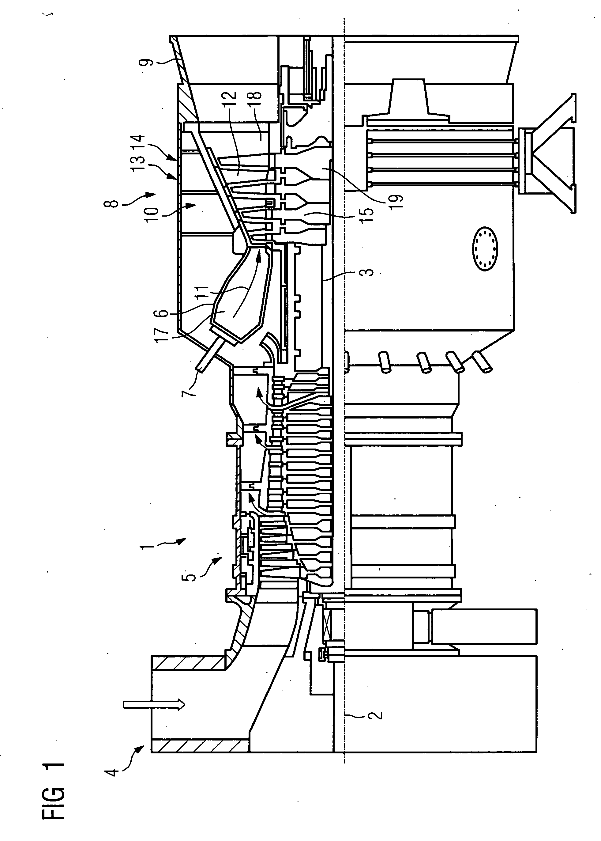
[0033]FIG. 1 shows a partial longitudinal section through a gas turbine 1. In its interior, it has a rotor 3 which is mounted such that it can rotate about an axis of rotation 2 and is also referred to as the turbine rotor. An intake casing 4, a compressor 5, a toric annular combustion chamber 6 with a plurality of burners 7 arranged rotationally symmetrically with respect to one another, a turbine unit 8 and an exhaust gas casing 9 follow one another along the rotor 3. The annular combustion chamber 6 forms a combustion space 17 which is in communication with an annular hot gas duct 18. There, four successive turbine stages 10 form the turbine unit 8. Each turbine stage 10 is formed from two blade rings. As seen in the direction of flow of a hot gas 11 generated in the annular combustion chamber 6, a guide vane row 13 is in each case followed by a row 14 formed from gas turbine rotor blades 15 in the hot gas duct 18. The guide vanes 12 are secured to the stator, whereas the gas tur...


PUM


Abstract

The invention relates to a gas turbine blade or vane ring having a supporting structure and gas turbine blades or vanes secured to it. The gas turbine blades or vanes have a blade or vane root, which is successively adjoined by a platform and then a blade profile which is curved in the longitudinal direction, the blade or vane root running in the longitudinal direction of the blade profile, and the platform having two platform longitudinal edges which are bent parallel and run in the longitudinal direction. To provide an alternative gas turbine blade or vane ring with simplified assembly, it is proposed that the blade or vane root be shaped in such a manner that the suction-side or pressure-side blade or vane root surface of the associated platform longitudinal edge be curved convexly or concavely, respectively. Moreover, the invention relates to the use of a gas turbine blade or vane ring of this type.

Description

CROSS REFERENCE TO RELATED APPLICATION [0001] This application claims the benefit of U.S. Provisional Patent Application Ser. No. 60 / 702,358, filed Jul. 25, 2005.FIELD OF THE INVENTION [0002] The invention relates to a gas turbine blade or vane having a blade or vane root which is profiled in cross section and is successively adjoined by a platform and then a blade profile which is curved in the longitudinal direction, the blade or vane root running in the longitudinal direction of the blade profile, and the platform having two platform longitudinal edges which are bent parallel and run in the longitudinal direction. Furthermore, the invention relates to a platform element for a gas turbine blade or vane ring of a gas turbine, having a profiled platform root and a platform plate, which has two bent longitudinal edges and in which the platform plate and the platform root extend in a longitudinal direction. Moreover, the invention relates to a supporting structure for securing gas tur...

Claims


Application Information

Patent Timeline
IPC IPC(8): F01D5/30
CPCF01D5/3007F01D11/008F05D2250/711F05D2250/71F05D2250/712F05D2240/80
Inventor BEECK, ALEXANDER RALPHIRMISCH, STEFAN
Owner SIEMENS AG
Learn More