
Dichroic prism, and prism unit and image projection apparatus employing same

Inactive Publication Date: 2007-01-25
KONICA MINOLTA OPTO
View PDF0 Cites 3 Cited by
  • Summary
  • Abstract
  • Description
  • Claims
  • Application Information

AI Technical Summary

Benefits of technology

[0007] In view of the conventionally experienced inconvenience mentioned above, it is an object of the present invention to provide a projector that, despite employing a micro display device, does not suffer from deterioration of projected images even when kept being used at a high output.
[0009] To achieve the above object, according to one aspect of the present invention, in a dichroic prism, a dichroic film formed on a prism base member contains 10% by volume or more of a high-thermal-conductivity substance having a thermal conductivity of 20 W / mK or more at a temperature of 300 K. With this design, even when the dichroic film is heated locally through absorption of light, the heat conducts all over the dichroic film, making an uneven temperature distribution less likely. Thus, even when the dichroic prism is used in an image projection apparatus that yields a high output of light of 15 000 lumens or more, or when illumination light and projection light travel along different optical paths within the prism base member, image deterioration can be minimized. Moreover, the dichroic prism according to the invention exhibits low angle-of-incidence dependence, reducing the amount of so-called stray light, that is, the light that cannot pass through the dichroic prism along the path from illumination to projection. Accordingly, the heat produced by stray light is also reduced.
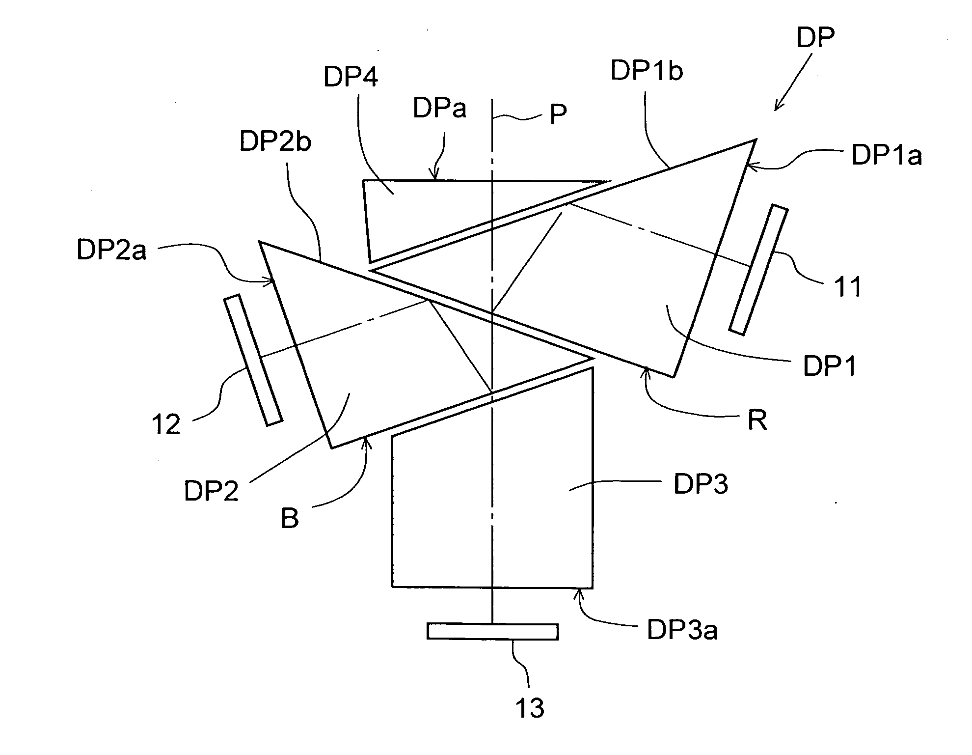
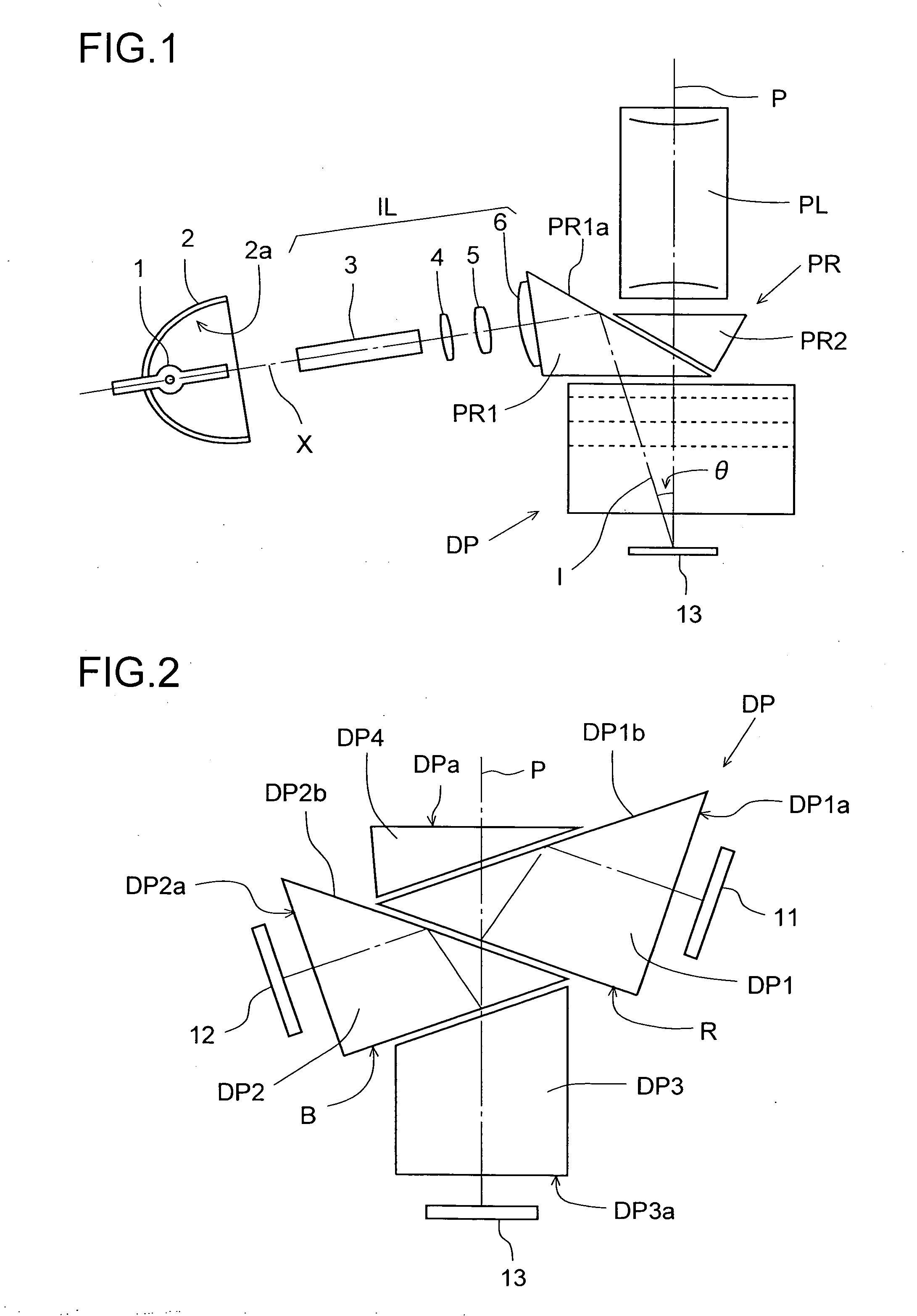
[0011] According to another aspect of the present invention, a prism unit that separates white light into light of different wavelength bands and / or that integrates light of different wavelength bands into light traveling along the same optical path is provided with a first prism having a first dichroic film, a second prism having a second dichroic film, and a third prism. Here, the first dichroic film is disposed to face the second prism, and the second dichroic film is disposed to face the third prism. Moreover, at least one of the first and second dichroic films contains 10% by volume or more of a high-thermal-conductivity substance having a thermal conductivity of 20 W / mK or more at a temperature of 300 K. Furthermore, the prism unit permits a luminous flux of 15 000 lumens or more to pass therethrough.

Problems solved by technology

Inconveniently, however, when conventional projectors are kept being used at such high outputs, the projected images gradually deteriorate.

Method used


Image

  • Dichroic prism, and prism unit and image projection apparatus employing same
  • Dichroic prism, and prism unit and image projection apparatus employing same
  • Dichroic prism, and prism unit and image projection apparatus employing same

Examples


example 1

[0042] A dichroic film having a layer structure as shown in Table 2 was formed on a surface of a prism base member (having an absorptance of 0.29%). This dichroic film was designed to reflect red light and transmit blue and green lights, and had high-refractive-index layers and low-refractive-index layers laid alternately on one another by IAD. The high-refractive-index layers were Nb2O5 films, and the low-refractive-index layers were Al2O3 films. The volume proportion of Al2O3 in this dichroic film was 42.5%, and its volume proportion in the low-refractive-index layers was 100%. The refractive index ratio NH / NL between the high- and low-refractive-index layers was 1.34. This dichroic prism was used as the first prism DP1 (shown in FIG. 2).

[0043] A dichroic film having a layer structure as shown in Table 3 was formed on a surface of a prism base member (having an absorptance of 0.29%). This dichroic film was designed to reflect blue light and transmit green light, and had high-refr...

example 2

[0047] Except that the prism base members had an absorptance of 0.49%, the first and second prisms DP1 and DP2 were fabricated in the same manner as in Example 1. Then, as in Example 1, by using the thus fabricated first and second prisms DP1 and DP2, the prism units shown in FIGS. 1 and 2 were assembled, and were built into an image projection apparatus. Then, by using as a light source a 6 kW xenon lamp, lights of different colors, namely red (R), green (G), and blue (B), were projected onto a screen, and the quality of the resulting images was visually evaluated. The results of evaluation are shown in Table 6.

[0048] As will be clear from Table 6, the image projection apparatus employing the dichroic prisms and the prism units of Example 2 offered satisfactory image quality immediately after lighting was started. One hour after lighting was started, the quality of the images of lights of different colors was still practically acceptable, though slightly lower than that obtained i...


PUM


Abstract

A dichroic film formed on a prism base member contains 10% by volume or more of a high-thermal-conductivity substance having a thermal conductivity of 20 W / mK or more at a temperature of 300 K. Preferably, the dichroic film is composed of high- and low-refractive-index layers laid alternately on one another, and the low-refractive-index layers contain 20% by volume or more of the high-thermal-conductivity substance. For lower angle-of-incidence dependence and higher light use efficiency, preferably, the following conditions: NL≧1.58 and NH / NL≧1.33, where NL represents the refractive index of the low-refractive-index layers, and NH represents the refractive index of the high-refractive-index layers.

Description

[0001] This application is based on Japanese Patent Application No. 2005-213691 filed on Jul. 25, 2005 the contents of which are hereby incorporated by reference. BACKGROUND OF THE INVENTION [0002] 1. Field of the Invention [0003] The present invention relates to a dichroic prism, and more particularly to a dichroic prism suitable for use in an image projection apparatus that offers a high output of light. [0004] 2. Description of Related Art [0005] In recent years, research and development have been done on projectors (image projection apparatuses) that project image data in the form of digital data by the use of a micro display device (image display device) such as a reflective liquid crystal panel or a DMD (digital micromirror device). A number of such projectors have already been put into practical use. Such projector can project high-quality images with natural colors without image deterioration, and thus have recently come to be used in movie theaters and the like in place of ...

Claims


Application Information

Patent Timeline
IPC IPC(8): G02B27/12
CPCG02B5/285G02B7/008G02B27/145G02B27/142G02B27/1026
Inventor SAWAI, YASUMASATAGUCHI, TOMOKAZUNOMURA, YASUYUKI
Owner KONICA MINOLTA OPTO
Learn More