Eureka AIR delivers breakthrough ideas for toughest innovation challenges, trusted by R&D personnel around the world.

Power systems for transportation and residential uses

Inactive Publication Date: 2007-01-25
CHROBAK DENNIS S
View PDF38 Cites 5 Cited by
  • Summary
  • Abstract
  • Description
  • Claims
  • Application Information

AI Technical Summary

Benefits of technology

[0016] One advantage of this invention is that Earth's dependency on fossil fuels can be greatly diminished.
[0017] Another advantage of this invention is that electromagnetic radiation can be used as an energy source in an efficient and economic manner.
[0018] Another advantage of this invention is that the energy source does not create pollution.

Problems solved by technology

We have an energy problem.
As is now well known, the Earth's fossil fuel resources are limited.
Meanwhile, energy consumption rates continue to rise.
With the electromagnetic radiation available in Earth's magnosphere the next issue becomes how to receive this energy in a manner that can be readily used.
I believe, however, that the use of such electric motors (that replace or are added on to well-known internal combustion engines (ICEs)) are not the most advantageous way to use this technology.

Method used


Image

  • Power systems for transportation and residential uses
  • Power systems for transportation and residential uses
  • Power systems for transportation and residential uses

Examples


Embodiment Construction

[0033] Referring now to the drawings wherein the showings are for purposes of illustrating one or more embodiments of the invention only and not for purposes of limiting the same, FIG. 2 shows a vehicle 10 equipped with the power wheel system 100 of this invention. It should be noted that while the vehicle 10 shown is an automobile, the power wheel system 100 of this invention will work well with any vehicle including trucks, buses, motorcycles, off-road vehicles, lawn mowers and the like. The vehicle 10 may have a frame 12 and a body 14 attached to the frame 12. The vehicle 10 may have all other conventional components which are well-known and, thus, will not be described in great detail here. The power wheel system 100 of this invention can be attached to a conventional vehicle, as discussed further below, or to vehicles having very different designs. Because my invention eliminates the need for ICEs, conventional electric motors, hybrid ICE / electric motors, conventional drive tra...


PUM


Abstract

A power wheel system includes a first wheel member that is attachable to a vehicle, an electric motor that selectively rotates the first wheel member and that is mounted at least partially within the first wheel member and a receiver that is attachable to the vehicle that receives wireless power from a power source, preferably electromagnetic radiation energy from the Earth's magnosphere. The power wheel system may also include a first transformer that receives an input voltage from the receiver and supplies a corresponding output voltage to the electric motor. This transformer may be positioned at least partially within the wheel member. The power wheel system may also include a control mechanism that is used to control the power wheel system. In another embodiment some of the same components can be arranged to provide a power residence system.

Description

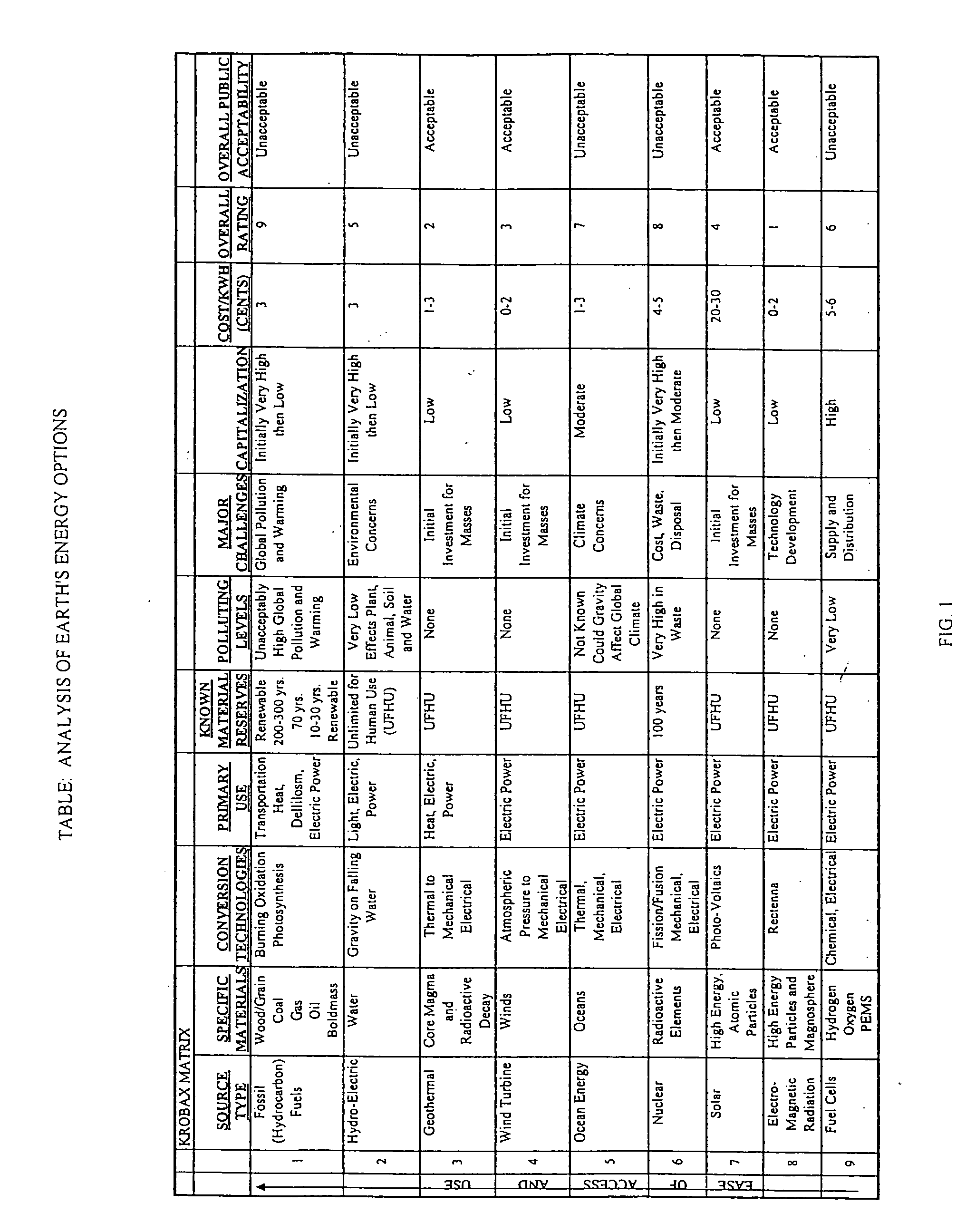
I. BACKGROUND OF THE INVENTION [0001] A. Field of Invention [0002] This invention pertains to the art of methods and apparatuses regarding the harnessing of energy for human use and more specifically to methods and apparatuses regarding the use of electromagnetic radiation energy via wireless resources for transportation and residential energy purposes. [0003] B. Description of the Related Art [0004] We have an energy problem. As is now well known, the Earth's fossil fuel resources are limited. Meanwhile, energy consumption rates continue to rise. In a recent public broadcast, a spokesman indicated that Saudi Arabia cannot meet the United States oil supply requirements beyond 2015. We simply have no option but to find new sources of energy. Many people are aware of this problem and are working hard to resolve it. FIG. 1 is a table showing my analysis of the energy options before us. I call this the KROBAX MATRIX. The first column shows the nine primary energy source options. The res...

Claims


Application Information

Patent Timeline
IPC IPC(8): B60K1/00
CPCB60K6/52B60K7/0007B60K16/00B60K2007/0038Y02T10/90H01Q1/325H02K7/14Y02T10/6265B60K2007/0092B60L2200/12B60L2200/18B60L2200/40B60L2200/46B60L2220/44B60L50/20Y02T10/62Y02T10/64
Inventor CHROBAK, DENNIS S.
Owner CHROBAK DENNIS S
Why Eureka
Eureka Blog
Learn More