
Remote digital subscriber line access multiplexer

a digital subscriber and multiplexer technology, applied in the field of remote digital subscriber line access multiplexers, can solve the problems of insufficient transmission data rate for so-called full service network, and insufficient need for transmission data rate provided by adsl technology, and achieve cost-effective effects

Inactive Publication Date: 2007-01-18
WIRELESS LAN SYST
View PDF7 Cites 20 Cited by
  • Summary
  • Abstract
  • Description
  • Claims
  • Application Information

AI Technical Summary

Benefits of technology

[0010] It is an object of the present invention to provide a solution for connecting DSLAMs to each other efficiently.
[0011] Further, it is an object of the present invention to provide a solution to adjust the number of customer connections in a flexible manner.
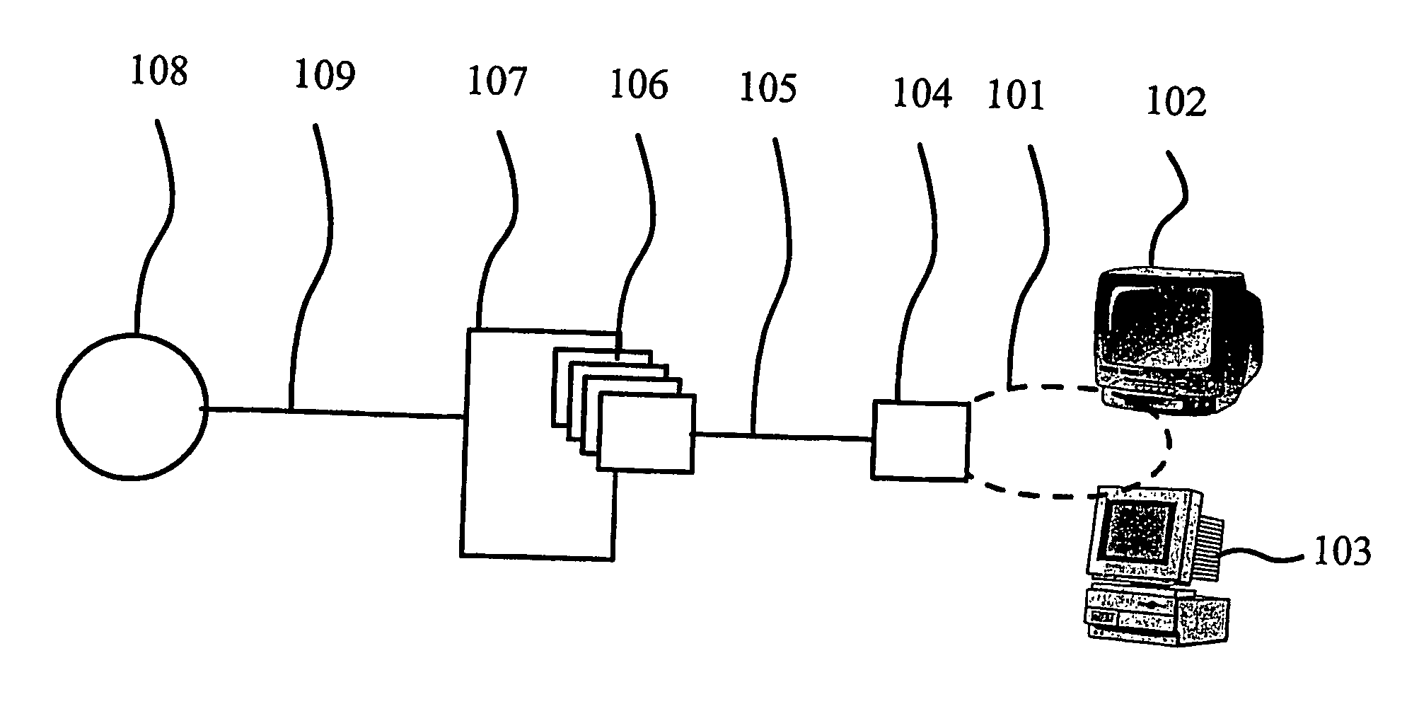
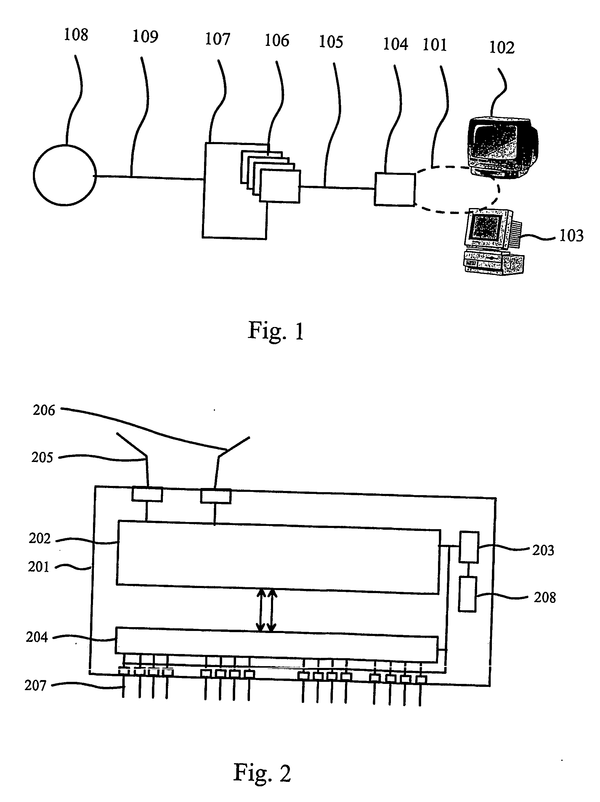
[0032] The present invention provides various advantages over the prior art solutions. The system of the present invention is capable of providing DSL services to new customers more cost efficient manner than the prior art solutions, by connecting a remote DSLAM via high data rate connection or lower data rate connection to existing DSLAM (which is essentially close to the customers). This approach also provides flexibility to the number of the customers of the DSL services.

Problems solved by technology

This transmit speed does not satisfy the needs of the present day services that are provided e.g., through the Internet.
Even though the present ADSL technology is capable for the transmission data rate up to 9.0 Mbps for downstream and 640 kbps for upstream, the transmission data rate is not sufficient for so called full service network.
Also when the number of subscribers increases, the need for transmission data rates provided by ADSL technology may become insufficient.
This solution provides a possibility to bring the high data rate connections to more distant subscribers, but the investments requires quite a lot of money especially when the existing twisted-pair copper telephone lines should be replaced by the fiber.
Also the number of possible subscribers is limited to the number of possible connections provided by the DSLAM in the street cabinet.
This solution, however, is not preferable, because of the rapid decrease of the transmission data rate (especially when the DSL service provider wishes to provide the full service transmission data rates for the subscribers) and they are essentially difficult to install.
Due to the need of numerous repeaters in the twisted-pair copper telephone line, the costs of the investment increases tremendously especially on the areas where the subscribers are situated at relatively long distance from each other.
Even though there has been described various solutions for providing higher transmission data rates to more distant customers, the solutions have high set up costs for a service provider, they are rigid for adjusting to the number of subscribers, and / or they require the existing twisted-pair copper telephone lines to be replaced by new fiber lines (providing higher data transmission capacity).

Method used


Image

  • Remote digital subscriber line access multiplexer
  • Remote digital subscriber line access multiplexer
  • Remote digital subscriber line access multiplexer

Examples


first embodiment

[0055] In the first embodiment, the connection 303 between the first remote DSLAM 301 and the second remote DSLAM 305 is electrical connection capable of transmitting the data on Gbit rate. In this embodiment, the first remote DSLAM 301 has another high data rate connection 302, which is an optical fiber capable of transmitting the data on Gbit rate. The second remote DSLAM 305 has corresponding high data rate connection (optical fiber) 306. The high data rate connections 302 and 306 may be connected to e.g., central office of the DSL service provider or to still another remote DSLAM (not shown).

[0056] The first remote DSLAM 301 has further lower data rate connections 304 for connecting the CPEs (Customer Premises Equipment) 308 to the first remote DSLAM 301. The lower data rate connections 304 are twisted-pair copper telephone lines. The second remote DSLAM 305 has corresponding twisted-pair copper telephone lines 307 for connecting the CPEs 309 to the second remote DSLAM 305.

[005...

second embodiment

[0058] In the second embodiment according to the concept of the present invention as shown in FIG. 3, the high data rate connection 303 is optical fiber. In this case the high data rate connections 302 and 306 may be connected e.g., to a node in the data network (not shown) or to another DSLAM(s).

[0059] The need for this kind of solution may arise when possible new customer would like to become subscribers of the service and there is no capacity available in the present remote DSLAM. In prior art solutions, the service provider should have inserted another remote DSLAM next to the first remote DSLAM and provide an optical fiber connection from the central office to the new remote DSLAM. Contrary to the prior art solutions, the present invention provides a solution in which a new remote DSLAM can be provided to serve new subscribers when the capacity of the first remote DSLAM is not sufficient.

[0060] Also by chaining the remote DSLAMs in parallel, the service provider may provide fu...


PUM


Abstract

The present invention relates to a remote digital subscriber line access multiplexer (DSLAM), and to DSL systems providing data network services to customers. The remote DSLAM has at least two high data rate connections, from which one of the high data rate connections is an optical connection and another one of the high data rate connections is an electrical connection. Alternatively, the connections may be of the same type. The remote DSLAM also comprises a lower data rate connection(s), which is preferably a twisted-pair copper line connection. The remote DSLAM is connected to a central office, a data network node, or another remote DSLAM. The connection to the central office is preferably an optical connection, the connection to the data network node is preferably an electrical connection, and the connection to another remote DSLAM may be an optical, an electrical, or a twisted-pair copper line connection.

Description

TECHNICAL FIELD OF THE INVENTION [0001] The present invention relates to DSL systems, and more particularly to remote DSLAMs (Digital Subscriber Line Access Multiplexers), their connections, and a system for connecting DSLAMs to each other. BACKGROUND OF THE INVENTION [0002] The most used method for transmitting and receiving (in the user's end) data is a voice grade data modem. The capacity for transmitting and receiving the data of the voice grade data modem over a common telephone line is presently up to 56 kbps. This transmit speed does not satisfy the needs of the present day services that are provided e.g., through the Internet. For providing data on a higher transmission data rate, there is provided various solutions that utilize the existing twisted-pair copper telephone lines. [0003] The most commonly used solution for transmitting the data on a higher transmission data rate is based on ADSL (Asynchronous Digital Subscriber Line) technology. Even though the present ADSL tec...

Claims


Application Information

Patent Timeline
IPC IPC(8): H04L12/66H04J3/04H04L12/28H04M11/06H04Q3/60H04Q11/04
CPCH04L12/2892H04M11/062H04Q3/60H04Q2213/13381H04Q2213/13039H04Q2213/13099H04Q11/04
Inventor TIRRI, TOMI
Owner WIRELESS LAN SYST
Learn More