
Porous PTFE materials and articles produced therefrom

a technology of porous ptfe and materials, which is applied in the field of porous ptfe membranes, can solve the problems of reducing the permeability of liquid or gas through the membrane, reducing the permeability of the membrane, and reducing the efficiency of the capture of small particles, so as to achieve low flow resistance, small pore size, and high strength

Active Publication Date: 2007-01-18
WL GORE & ASSOC INC
View PDF5 Cites 127 Cited by
  • Summary
  • Abstract
  • Description
  • Claims
  • Application Information

AI Technical Summary

Benefits of technology

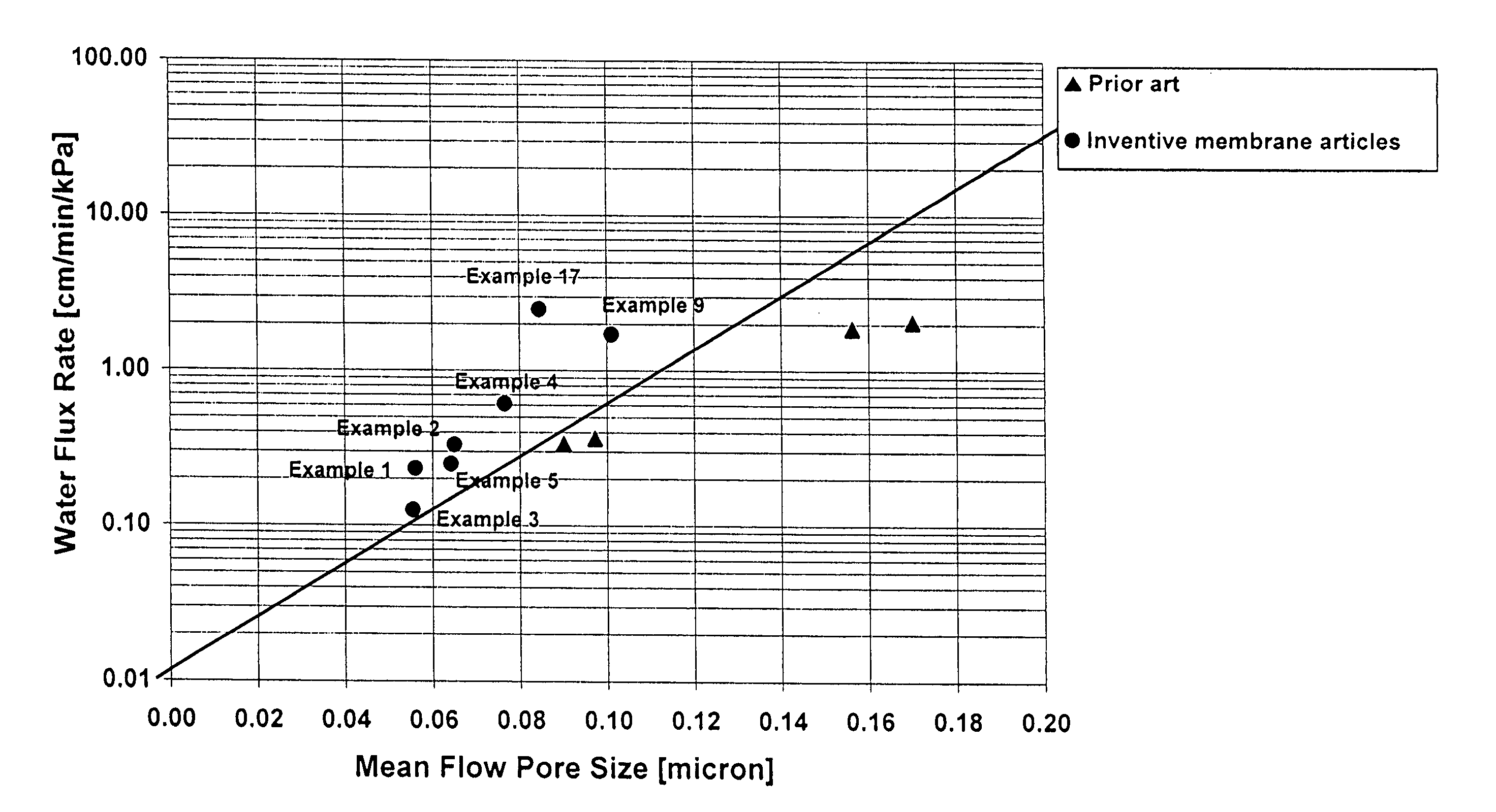
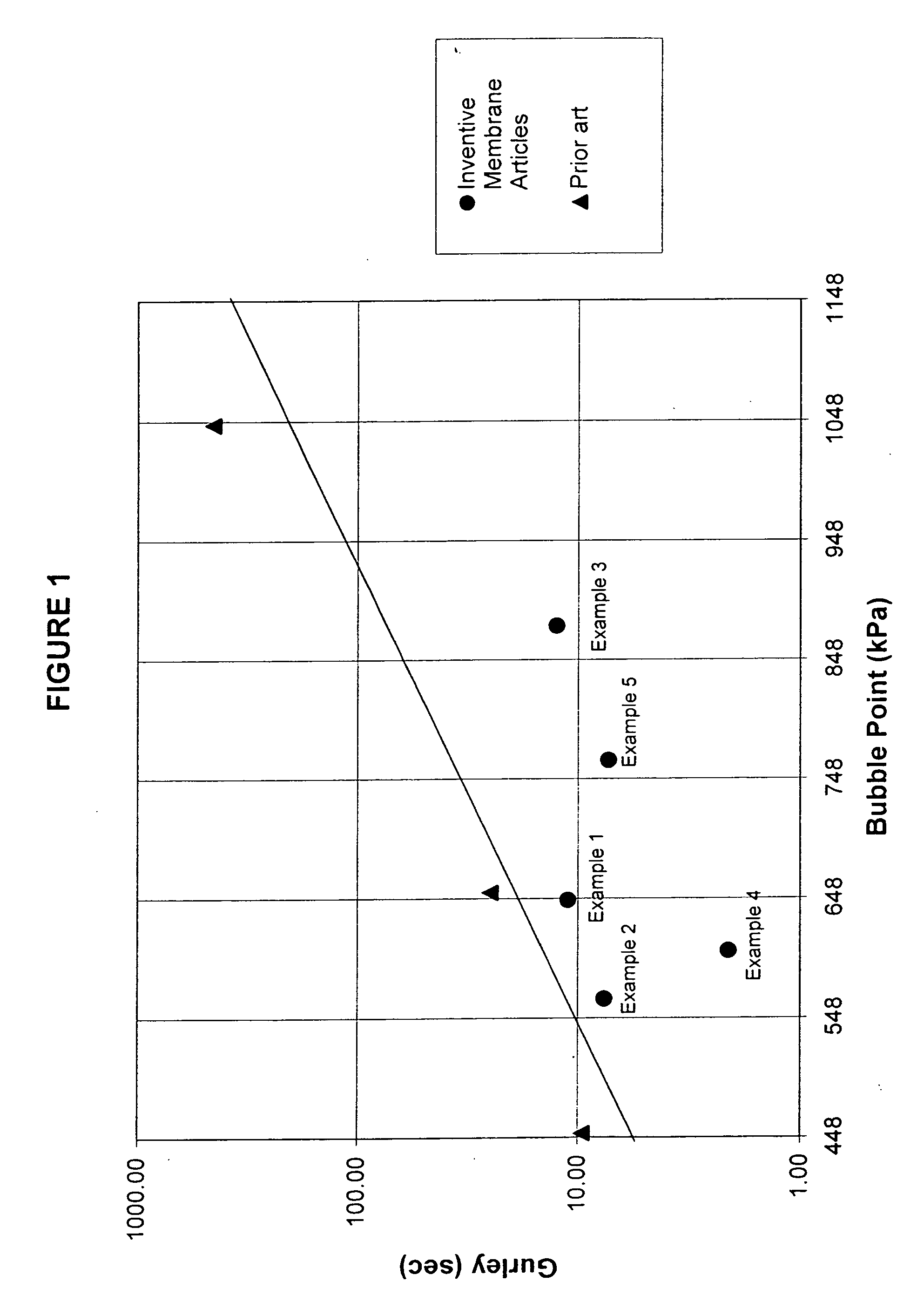
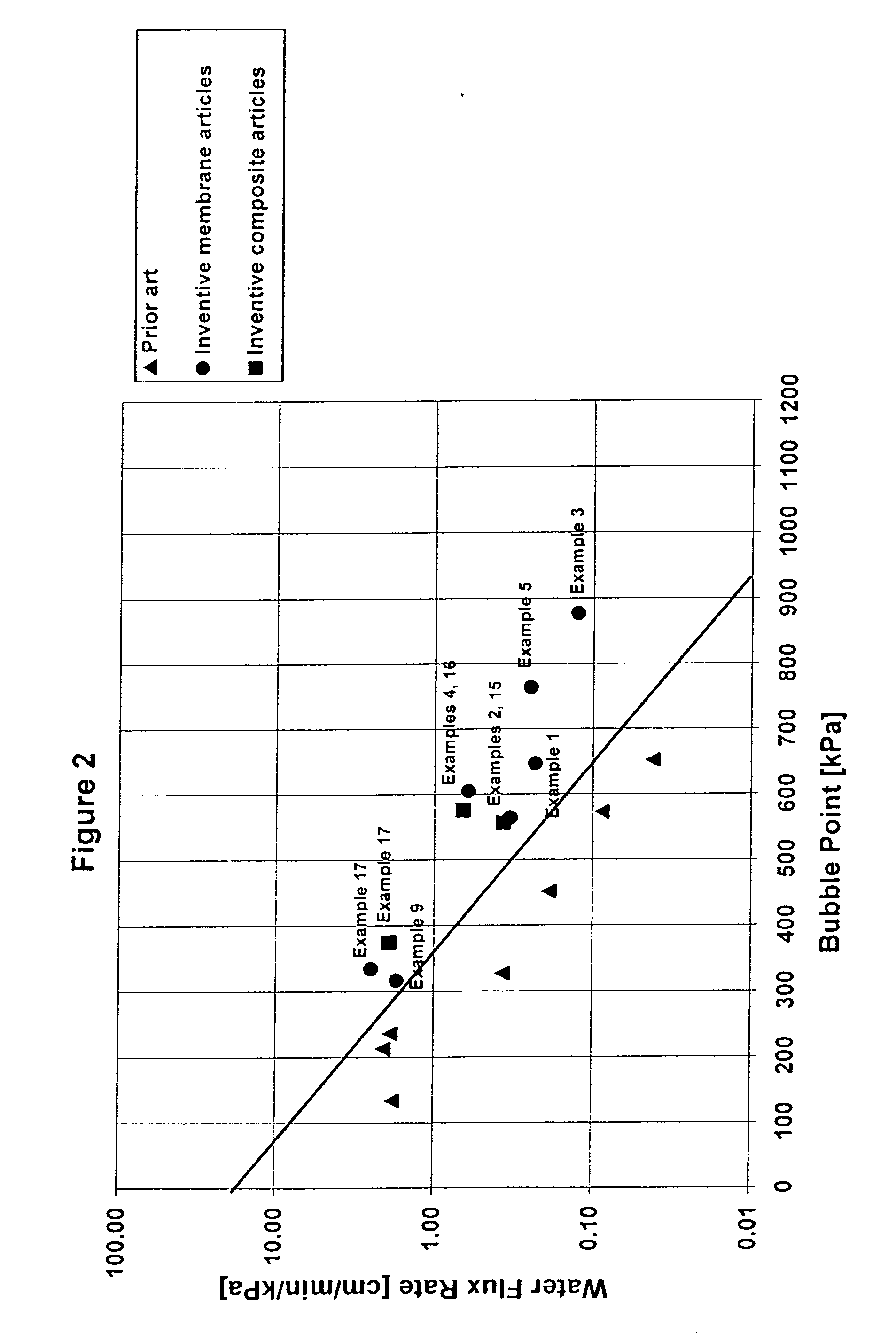
[0013] The present invention is directed to novel porous PTFE membranes possessing a unique combination of high strength, low flow resistance, and small pore size. Further, the present invention is directed to unique high performance filter materials and vent constructions, including those suitable for venting applications, with filtration performance which has been heretofore unachievable.

Problems solved by technology

Typically, optimizing either filtration efficiency or permeability comes at the expense of compromising the other.
For example, in order to capture smaller particles, the membrane must possess small pores, but the smaller pore size typically increases flow resistance and therefore decreases the liquid or gas permeability through the membrane.
Similarly, increasing flow through the membrane is readily achieved by increasing the pore size of the filter media, but in doing so the membrane captures fewer particles and is less efficient in the capture of smaller particles.
These materials, albeit having improved filtration performance compared to predecessor membranes, have limitations in their ability to satisfy increasingly demanding commercial needs.
The larger pore size results in lower flow resistance through the membranes, but, as noted above, at the expense of filtration efficiencies, especially for smaller particles.
Further stretching tends to decrease membrane thickness which can result in a reduction in flow resistance.

Method used


Image

  • Porous PTFE materials and articles produced therefrom
  • Porous PTFE materials and articles produced therefrom
  • Porous PTFE materials and articles produced therefrom

Examples


example 1

[0062] Fine powder of PTFE polymer (Daikin Industries, Ltd., Orangeburg, N.Y.) was blended with Isopar K (Exxon Mobil Corp., Fairfax, Va.) in the proportion of 0.196 g / g of fine powder. The lubricated powder was compressed in a cylinder to form a pellet and placed into an oven set at 70° C. for approximately 12 hours. Compressed and heated pellets were ram extruded to produce tapes approximately 15.2 cm wide by 0.73 mm thick. Three separate rolls of tape were produced and layered together between compression rolls to a thickness of 0.76 mm. The tape was then transversely stretched to 56 cm (i.e., at a ratio of 3.7:1), restrained, then dried in an oven set at 270° C. The dry tape was longitudinally expanded between banks of rolls over a heated plate set to a temperature of 340° C. The speed ratio between the second bank of rolls and the first bank of rolls, and hence the expansion ratio, was 8:1. The longitudinally expanded tape was then expanded transversely at a temperature of appr...

example 2

[0064] Fine powder of PTFE polymer (Daikin Industries, Ltd., Orangeburg, N.Y.) was blended with Isopar K (Exxon Mobil Corp., Fairfax, Va.) in the proportion of 0.196 g / g of fine powder. The lubricated powder was compressed in a cylinder to form a pellet and placed into an oven set at 70° C. for approximately 12 hours. The compressed and heated pellets were ram extruded to produce tapes approximately 15.2 cm wide by 0.73 mm thick. Three separate rolls of tape were produced and layered together between compression rolls to a thickness of 0.76 mm. The tape was then transversely stretched to 56 cm (i.e., at a ratio of 3.7:1), restrained, then dried at a temperature of 270° C. The dry tape was longitudinally expanded between banks of rolls in a heat zone set to a temperature of 340° C. The speed ratio between the second bank of rolls to the first bank of rolls, and hence the expansion ratio, was 13:1. The longitudinally expanded tape was then expanded transversely at a temperature of app...

example 3

[0066] Fine powder of PTFE polymer as described and taught in U.S. Pat. No. 6,541,589 was blended with Isopar K (Exxon Mobil Corp., Fairfax, Va.) in the proportion of 0.202 g / g of fine powder. The lubricated powder was compressed into a cylinder to form a pellet and placed into an oven set at 70° C. for approximately 12 hours. Compressed and heated pellets were ram extruded to produce tapes approximately 15.2 cm wide by 0.73 mm thick. Three separate rolls of tape were produced and layered together between compression rolls to a thickness of 0.76 mm. The tape was then transversely stretched to 56 cm (i.e., at a ratio of 3.7:1), restrained, then dried at a temperature of 250° C. The dry tape was longitudinally expanded between banks of rolls over a heated plate set to a temperature of 345° C. The speed ratio between the second bank of rolls and the first bank of rolls was 15:1. The longitudinally expanded tape was then expanded transversely at a temperature of approximately 360° C. to...


PUM

PropertyMeasurementUnit
Fractionaaaaaaaaaa
Fractionaaaaaaaaaa
Fractionaaaaaaaaaa

Abstract

Novel porous PTFE membranes are described possessing a unique combination of high strength, low flow resistance, and small pore size. Additionally, unique constructions with superior filtration and venting properties incorporating porous PTFE membranes are described.

Description

RELATED APPLICATIONS [0001] The present application is a continuation application of U.S. patent application Ser. No. 11 / 184,706, filed Jul. 18, 2005.FIELD OF THE INVENTION [0002] The present invention relates to porous PTFE membranes with a combination of high air or liquid permeability and small pore size and filter materials made therefrom. DEFINITIONS [0003] As used in this application, the term “filtration efficiency” means the percentage of particles within a specified size range captured by a filtration material, or media, at a given flow rate. [0004] As used in this application, the term “flow” means the passage of a fluid through a membrane or filter material. The term “flow rate” means the volume of flow per unit time and the term “flow resistance” means the restriction of flow as results during flow through membranes or media with small pores. [0005] As used in this application, the term “permeability” means the ability to transmit fluids (liquid or gas) through the pores...

Claims


Application Information

Patent Timeline
IPC IPC(8): B01D71/26
CPCB01D39/1692B01D67/0027B01D69/02B01D69/12B01D71/36Y10T428/269B01D2325/02B01D2325/021B01D2325/20B01D69/06B01D2325/24B01D2325/00B32B5/022B32B5/024B32B5/026B32B5/16B32B5/245B32B7/12B32B27/12B32B27/322B32B3/02B32B3/26B32B2264/0257B32B2307/414B32B2307/54B32B2307/72B32B2307/724B32B2307/726B32B2307/732B32B7/05Y10T442/2139Y10T428/249954B01D67/00B01D2325/43B01D2325/0283
Inventor BACINO, JOHN E.HOBSON, ALEX R.STRID, JASON J.
Owner WL GORE & ASSOC INC
Learn More