Derotational brace for treatment of idiopathic scoliosis

Inactive Publication Date: 2007-01-11
HADASIT MEDICAL RES SERVICES & DEVMENT
View PDF13 Cites 12 Cited by
  • Summary
  • Abstract
  • Description
  • Claims
  • Application Information

AI Technical Summary

Benefits of technology

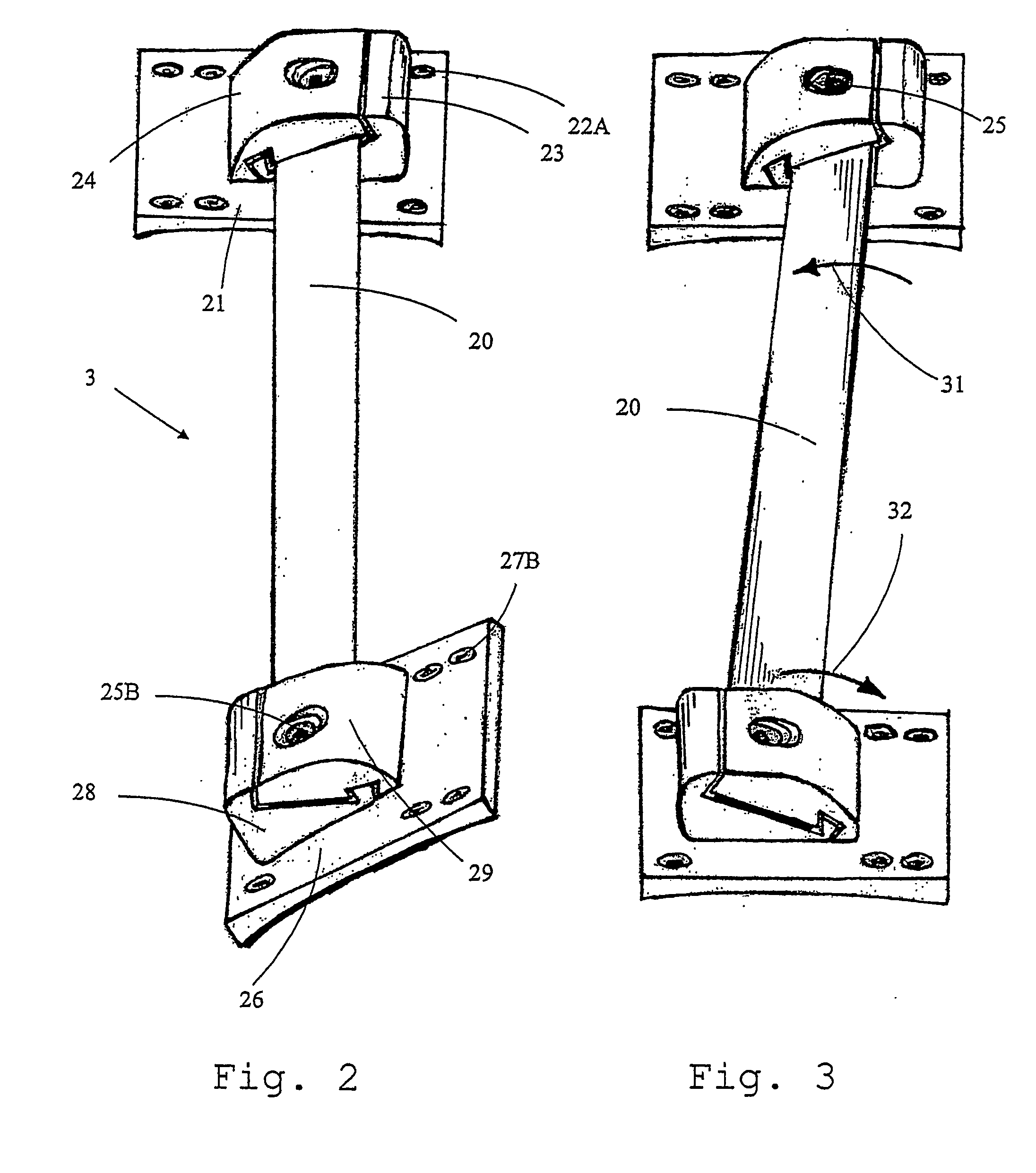
[0026] It is also in the scope of the present invention, wherein the working assembly comprises at least two sets of anchoring assembly, each anchoring assembly comprises the following three ingredients: (i) an anchoring device; (ii) a set of lower and upper clutches, and (iii), at least one fastening screw. The anchoring device is adapted to be immobilized firmly to the thoracic shell, or to the pelvic shell either directly or through any other additional component. The set of lower and upper clutches is adapted to clasp the working element, in a recess formed in between, the width of said recess is adapted to receiving the width of the working element with a small surplus gap on both sides of the working element. Lastly, the fastening screw connects between said anchoring device, said lower clutch, working element and said upper clutch in such a manner that a planar hinge is provided, enabling the working element to transmit a corrective de-rotational force which acts to pivot the anchoring assembly and in turn the surface of the brace to which it is attached, in the desired direction for correcting the scoliosis while, said working element can pivot in a limited course about said fastening screw and parallel to the patient back, due to the small surplus gap in the recess, on both sides of the working element. This pivoting of the working element is useful for providing the patient with some freedom in the lateral movements of his back and for allowing a correction of the posture by allowing the patient spine to straighten during the treatment period when the top of the patient back is brought to a more straight position, above its bottom.
[0028] According to one embodiment of the method according to the present invention, the step of adapting a pelvic shell and a thoracic shell for a patient to be treated is performed by (a) enveloping the patient with a soft cast, in such a manner that it encompasses the patient from the pelvis and upwards, along the spinal trunk; (b) dividing said casted whole brace to form thoracic and pelvic brace portions; (c) shaping said thoracic and pelvic brace portions (so as to form shells having contact areas with the patient body useful for transmitting pressures as uniformly as can be achieved, and adapted to the patient body, e.g. by minimizing (cutting) the brace area in the regions were the working element is not intended to affect a pressure, or e.g. cutting the brace region facing the breast in case of a female patient; (d) cutting said shaped thoracic and pelvic brace portions, so a side opening is provided, allowing for removal of the brace from the patient body; (e) fitting zippers or other closing arrangements on the rims of said openings; (f) connecting anchoring devices on the shells and (g) clutching a working element by said anchoring devices.
[0041] c. optionally shaping said thoracic and pelvic shell elements to a desired shape (e.g. for improving pressure distribution, or e.g. when the shape received by the casting comprise surplus portions which may unnecessarily disturb the patient);

Problems solved by technology

It includes a distortion of the abdominal and chest organs and therefore an alteration of their functional capabilities, alteration of a normal gait with associated pelvic obliquity and many other functional and psychosocial difficulties.
Therefore, the evaluation of medical methods of treatment is complicated and often empirical, and is based on the personal experience and beliefs of the surgeon.
One of the well-known problems with this treatment is the issue of compliance with brace wear.
These braces are considerably uncomfortable corset-like orthosis that apply non-constant and scattered twisting forces on the body of the patients.
Moreover, permanent loss of the natural flexibility of the spine because of the solid fusion of the spinal column is the price paid to protect the surgically achieved correction.
Complete failure to use the brace, however, has an adverse prognosis.
But control of the curves with apexes above T7, triple curves, and curves in excess of 45 degrees appeared poor.
One example of this may be the TriaC™ brace with a system of straps, but the amount of corrective forces that can be generated by this brace is limited and probably needs constant adjustment for effective use.

Method used


Image

  • Derotational brace for treatment of idiopathic scoliosis
  • Derotational brace for treatment of idiopathic scoliosis
  • Derotational brace for treatment of idiopathic scoliosis

Examples


Embodiment Construction

[0068] The following description is provided, alongside all chapters of the present invention, so as to enable any person skilled in the art to make use of said invention and sets forth the best modes contemplated by the inventor of carrying out this invention. Various modifications, however, will remain apparent to those skilled in the art, since the general principles of the present invention have been defined specifically to provide a scoliosis brace useful for providing a controlled and progressive correction of the scoliosis by using pure derotational forces, while retaining a high degree of freedom in 3-D movement of the spinal trunk of the patient.

[0069] The term ‘idiopathic scoliosis’ refers in the present invention to any malfunction of the trunk and / or the spinal column and to the various variants and subtypes, especially adolescent scoliosis.

[0070] The term ‘the brace’ refers in the present invention to any orthosis as hereto described and defined, adapted to treat said...


PUM


Abstract

A brace for correction of scoliosis is disclosed, comprising at least one thoracic shell element and a pelvic shell element and at least one working element having a main longitudinal axle to be oriented parallel to the trunk to be treated, anchored on one of its opposite ends to the thoracic shell element and on the other to the pelvic shell element, and having spring characteristics adapted to apply continuous de-rotational force about said longitudinal axle.

Description

FIELD OF THE INVENTION [0001] The present invention generally relates to a de-rotation brace for treatment of idiopathic scoliosis, and to a method for treating scoliosis and idiopathic scoliosis. BACKGROUND OF THE INVENTION [0002] Scoliosis, known also by the terms idiopathic scoliosis, spinal curvature and lardoscoliosis) is a deviation from a normal spine in three directions or planes: frontal (coronal), lateral (sagittal) and transversal (axial). While ten percent of the population will have some spinal curvature, no more than three promilles require extensive medical treatment. Scoliosis may be present due to underlying muscle or nerve problems, a defect in bone formation or due to unknown reasons, i.e., idiopathic scoliosis. Idiopathic scoliosis, and particularly its adolescent type, may affect up to three percent of the adolescent population. One treatment is provided by a scoliosis brace, which is an orthosis adapted to hold the spine in a straighter position. The brace is p...

Claims


Application Information

Patent Timeline
IPC IPC(8): A61F5/00A61F5/02
CPCA61F5/026A61F5/024
Inventor SIMANOVSKY, NAUM
Owner HADASIT MEDICAL RES SERVICES & DEVMENT
Why Eureka
Try Eureka