
Plastic tolerance compensating device

Inactive Publication Date: 2007-01-11
BOLLHOFF VERBINDUNGSTECHNIK GMBH
View PDF9 Cites 30 Cited by
  • Summary
  • Abstract
  • Description
  • Claims
  • Application Information

AI Technical Summary

Benefits of technology

[0004] It is the object of the present invention to provide a tolerance compensating assembly for automatically compensating tolerances in the spacing between two structural members which are to be clamped together which can be manufactured economically and of a configuration suitable for manufacturing from plastic.
[0007] The invention offers the possibility of a “complete plastic solution,” in which all three components are made of plastic. Manufacturing of the three components is thus a simple process, for example by injection molding.

Problems solved by technology

These known tolerance compensating assemblies are relatively expensive and those which make use of thermoplastic synthetics have the disadvantage of the clamping between the two structural members diminishing due to relaxation of the plastic.

Method used


Image

  • Plastic tolerance compensating device
  • Plastic tolerance compensating device
  • Plastic tolerance compensating device

Examples


Embodiment Construction

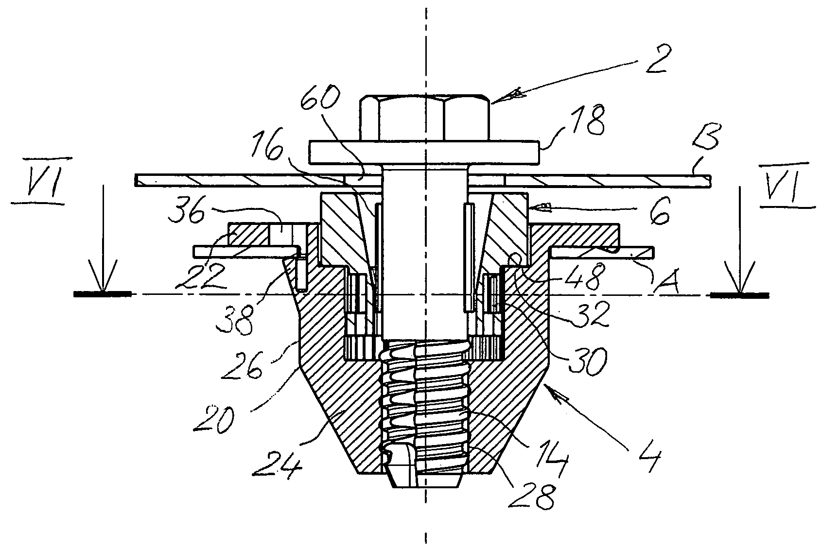
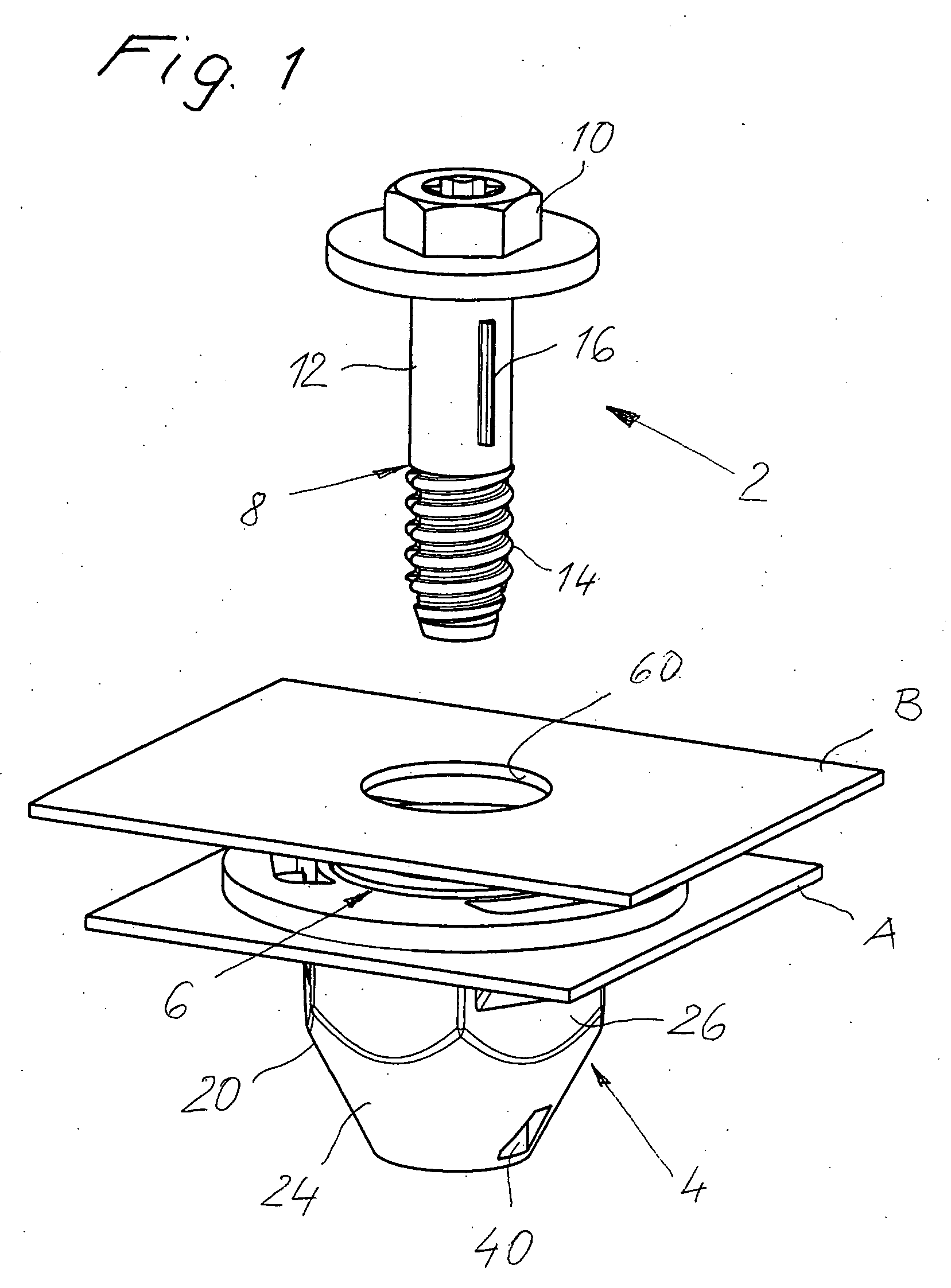
[0019] The tolerance compensating assembly shown in FIG. 1 serves to clamp the two structural members A, B and concurrently compensate the tolerance in the spacing between the said two structural members A, B. This spacing is subject to variation due to manufacturing and / or mounting tolerances in the pre-assembly or final assembly stage, which the tolerance compensating assembly can compensate.

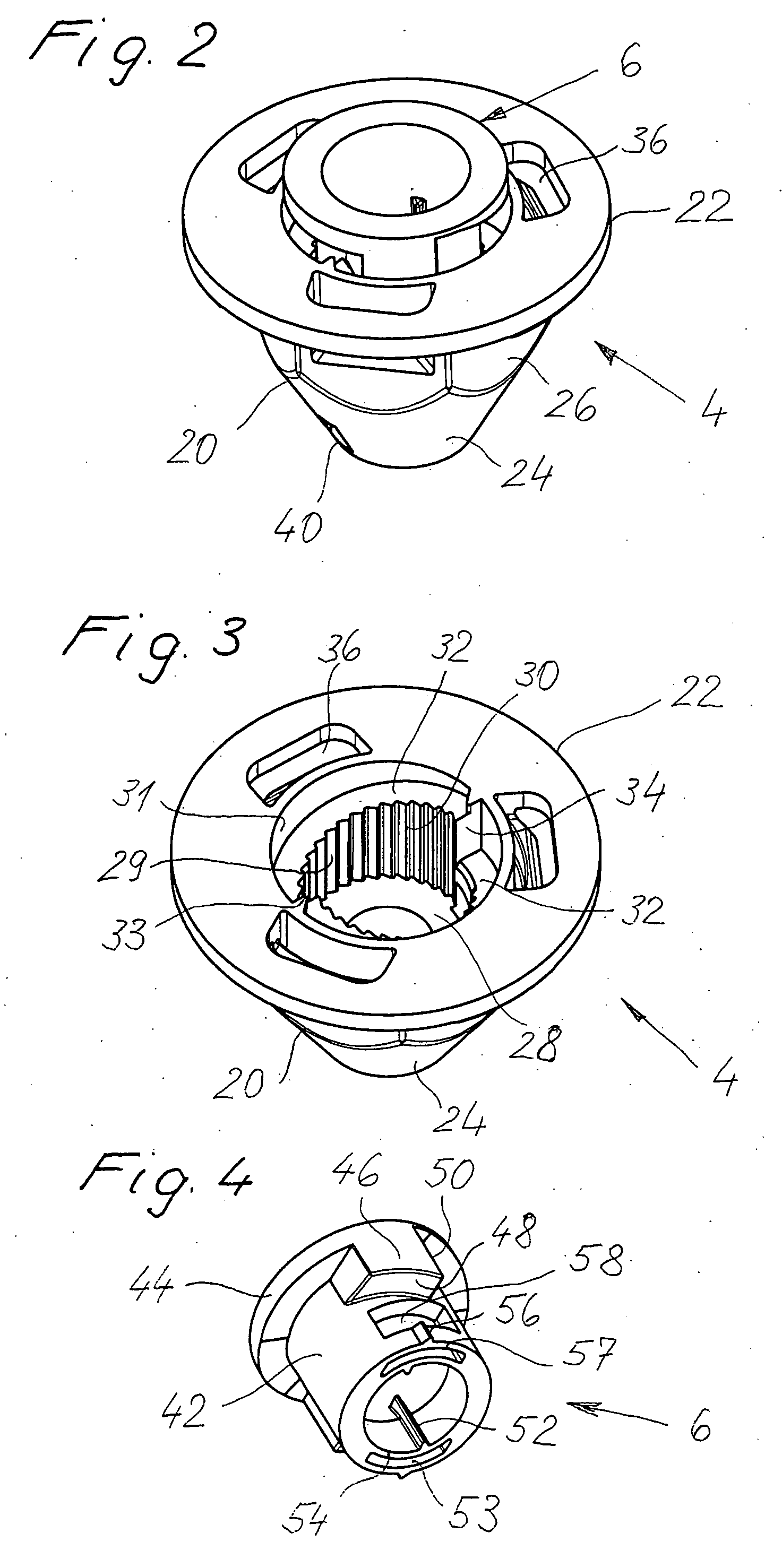
[0020] The tolerance compensating assembly consists of a mounting bolt 2, a receiving part 4 and an adjustment sleeve 6. The receiving part 4 and the adjustment sleeve 6 can be pre-assembled into a sub-unit as shown in FIG. 2, as will be described in greater detail below.

[0021] The mounting bolt 2 consists of a shaft 8 and a head 10. The head 10 can be configured as a conventional bolt head with the corresponding drive features. The shaft 8 consists of an essentially cylindrical, smooth-surfaced shaft portion 12 and a threaded portion 14. The threaded portion 14 has a self-tapping and / or for...


PUM


Abstract

The tolerance compensating assembly of the present invention comprises a mounting bolt 2, a receiving part 4, and an adjustment sleeve 6. The receiving part 4 can be fixed to a first of two structural members A, B and can be screwed with the mounting bolt 2 to clamp the structural members A, B. The adjustment sleeve 6 is supported on the receiving part 4 by ramped sliding surfaces 32, 48 and has at least one driver projection 52 which co-operates with a driver projection 16 of the mounting bolt 2 such that the adjustment sleeve 6 is also driven by the mounting bolt 2 upon the mounting bolt 2 being screwed into the receiving part 4 and is moved into abutment with the second structural member B to compensate tolerance as a function of a corresponding relative movement of the ramped sliding surfaces 32, 48.

Description

BACKGROUND OF THE INVENTION [0001] The present invention relates to a tolerance compensating assembly for automatically compensating tolerances in the spacing between two pre-mounted structural members or structural members to be mounted which are to be clamped together. [0002] A great number of such tolerance compensating assemblies are known, see for example EP 0 176 663 B1, DE 42 24 575 C2, DE 101 51 383 A1, DE-GM 201 190012 and DE-GM 203 14 003. They serve in compensating the tolerance between structural members which ensues in manufacturing and / or mounting. To this end, these tolerance compensating assemblies normally comprise an adjustment sleeve having a so-called drive portion which can enter into frictional contact connection with a mounting bolt. Upon rotating the mounting bolt, the adjustment sleeve is therefore also rotated until it fixedly abuts against one of the structural members to be clamped, whereupon given further rotation of the mounting bolt and the correspondi...

Claims


Application Information

Patent Timeline
IPC IPC(8): F16B43/02F16B5/02F16B35/04
CPCF16B5/0233F16B35/041F16B5/025
Inventor FIGGE, HANS-ULRICHMETTEN, ANDREASJODELEIT, MARTIN
Owner BOLLHOFF VERBINDUNGSTECHNIK GMBH
Learn More