Seamless tube piercing/rolling plug, seamless tube piercing/rolling apparatus, and seamless tube producing method therewith

Active Publication Date: 2007-01-11
NIPPON STEEL CORP
View PDF19 Cites 1 Cited by
  • Summary
  • Abstract
  • Description
  • Claims
  • Application Information

AI Technical Summary

Benefits of technology

[0094] A piercing test was performed with the piercing / rolling plug of the invention A in order to confirm the effect of the invention A. The test was performed with the inclined piercer shown in FIG. 1 while the cross angle γ was set to 10° and the feed angle β was set to 10°. FIG. 5 is a front sectional view showing a configuration in a lengthwise direction of the split plug used in the embodiment. The front part 21 and rear part 22 of the split plug were formed in combination of three steel types C to E whose chemical compositions are shown in Table 3. TABLE 3Chemical compositions (mass %,the remainder includesFe and unavoidable impurities)Steel typeCCrNiWMoC0.150.521.103.032.0D0.28—1.632.32.4E0.253.051.01——

Problems solved by technology

However, although ceramic has large compressive strength and a high wear-resistant property at high temperatures, ceramic is inferior in resistance to impact.
Therefore, there is a fear that the plug is broken from the front end in the piercing / rolling which is done in a harsh condition.
However, according to the study of the present inventors, when high alloy steel such as the Mo alloy and the Nb alloy is used for the front part of the split plug, the piercing efficiency is largely decreased because of a large coefficient of friction.
Therefore, the number of rotary forging is increased until the material to be rolled reaches the front end of the plug from onset engagement with inclined rolls, and the inside surface defects are easily generated by the Mannesmann fracture effect.
Even if any one of the plugs proposed in Japanese Patent Application Publication Nos. 2002-113507, 6-328105, and 2-63604 and the split plugs proposed in Japanese Patent Application Publication Nos. 10-180315 and 63-203205 is adopted, an enormous cost is required in view of the preparation of the plugs having sizes and types according to a tube making schedule.

Method used


Image

  • Seamless tube piercing/rolling plug, seamless tube piercing/rolling apparatus, and seamless tube producing method therewith
  • Seamless tube piercing/rolling plug, seamless tube piercing/rolling apparatus, and seamless tube producing method therewith
  • Seamless tube piercing/rolling plug, seamless tube piercing/rolling apparatus, and seamless tube producing method therewith

Examples


Embodiment Construction

[0079] In the above inventions, the inventions concerning the split plug including the oxide film shown in (1) to (5) are mainly referred to as invention A, the inventions concerning the seamless tube piercing / rolling apparatus including the oxide film shown in (6) to (10) are mainly referred to as invention B, and best modes for carrying out the present inventions will be described below.

[0080] 1. Mode for carrying out the invention A

[0081] (1) Best Mode of the Invention A

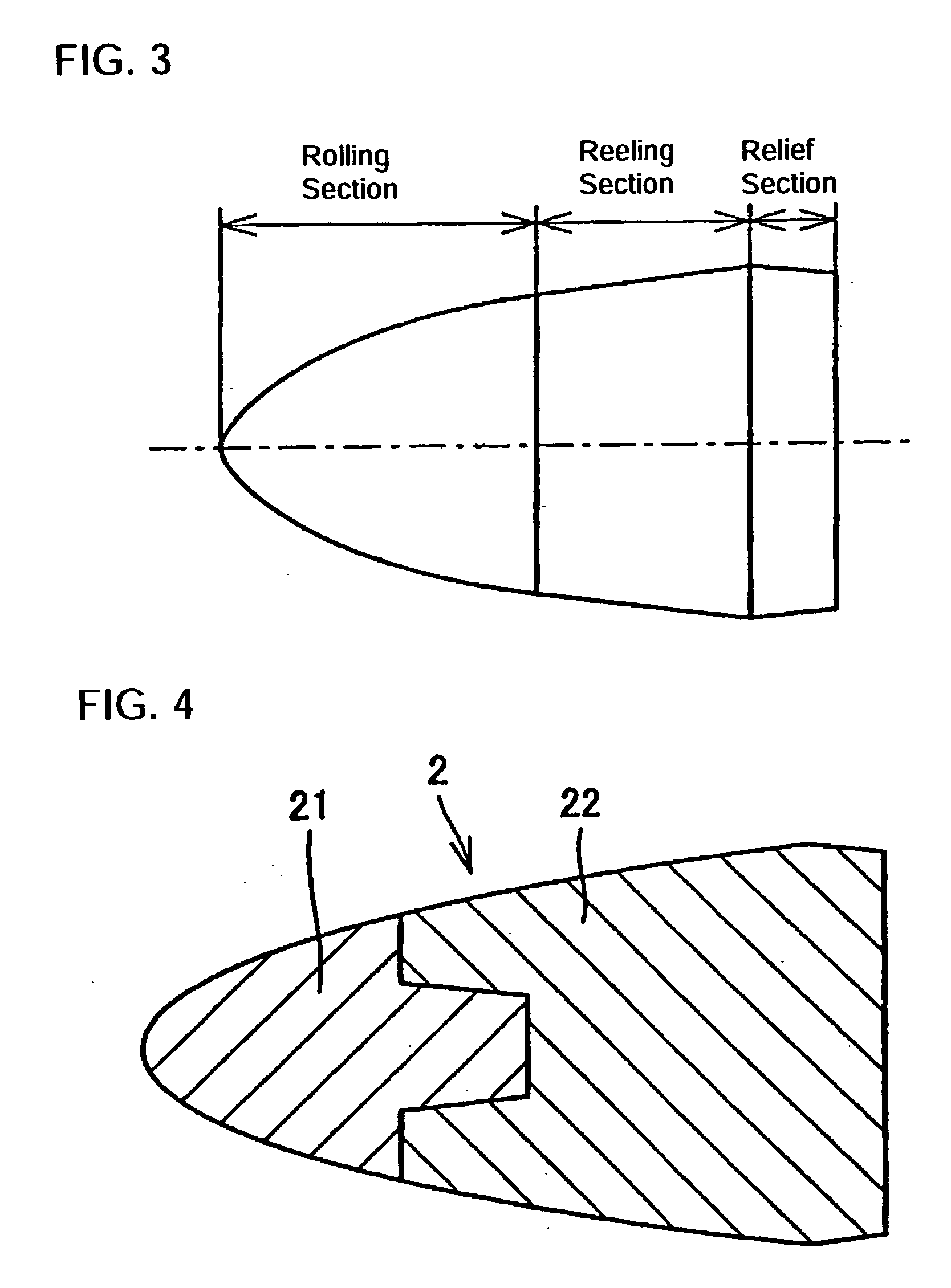
[0082] As shown in FIG. 4, a piercing / rolling plug of the invention A is a split plug 2 which is used while the split front part 21 and rear part 22 are jointed. The piercing / rolling plug of the invention A is characterized in that at least the front part 21 is made of low alloy steel and oxide films are formed on surfaces of the front part 21 and rear part 22. That is, the front part of the split plug is made of the low alloy steel, and the oxide films are formed on the surfaces of the front part 21 and rear p...


PUM

PropertyMeasurementUnit
Temperatureaaaaaaaaaa
Thicknessaaaaaaaaaa
Tensile strengthaaaaaaaaaa

Abstract

A seamless tube producing method uses a piercing / rolling plug wherein piercing / rolling is performed with an inclined rotary piercing mill while the seamless tube piercing / rolling plug is used as a piercing tool. In one mode, a front part and a rear part of the split plug are held as an integral plug, the front part being made of low alloy steel, and oxide films are formed on surfaces of the front part and rear part. In a second mode, the front part and / or rear part are replaceable via a removable mounting wherein a mandrel bar holding the plug goes through the rear part, the mandrel bar being coupled with the front part. A thickness of the oxide film formed in the front part can be 200 μm or more and the oxide film of the front part can be thicker than the oxide film of the rear part.

Description

TECHINICAL FIELD [0001] The present invention relates to a piercing / rolling plug suitable for an inclined rotary piercing method which is of a typical seamless tube producing method, and apparatus and method for producing the seamless tube therewith, more particularly to the piercing / rolling plug which has excellent durability and prevent generation of inside surface defects of the seamless tube in the piercing, a split plug whose front part and / or rear part can be replaced, and the apparatus and method for producing the seamless tube therewith. BACKGROUND ART [0002] In the so-called Mannesmann tube making process used as the typical method of producing the seamless tube, a billet heated to a predetermined temperature is fed to a piercer, and a hollow shell is produced by piercing an axial center portion of the solid billet. Then, the pierced hollow shell is passed through an elongating mill (mandrel mill) composed of five to eight stands to undergo a process of reducing the wall th...

Claims


Application Information

Patent Timeline
IPC IPC(8): B21B19/04B21B25/00B21B25/06
CPCB21B25/06B21B25/00
Inventor YAMAKAWA, TOMIOSHIMODA, KAZUHIRO
Owner NIPPON STEEL CORP
Why Eureka
Try Eureka