
Method for manufacturing a biosensor element and for testing the same

Inactive Publication Date: 2007-01-04
HITACHI SOFTWARE ENG
View PDF1 Cites 0 Cited by
  • Summary
  • Abstract
  • Description
  • Claims
  • Application Information

AI Technical Summary

Benefits of technology

[0010] The problems described above can be solved by providing a non-labeled / non-destructive detecting method as the following. That is, when a biomolecule is detected by a biosensor element, according to this method, the biosensor element is capable of detecting a biomolecule in a non-destructive manner, without labeling in advance the biomolecule to be detected. The problems above can also be solved by providing an analyzing method which is capable of evaluating a volume and structure of the probe biomolecules with high sensitivity and in a simple manner, the probe biomolecules being immobilized in a microarea on the sensor surface, in order to conduct a quality control of the biosensor element.
[0015] 4) a step which obtains either of a distance and an optical path length between the biosensor element and a source of the white light, either of which maximizes a modulation amount of the interference fringe,
[0026] 4) a step which obtains either of a distance and an optical path length between either of the biosensor element and the substrate, and a source of the white light, the distance maximizing a modulation amount of the interference fringe,

Problems solved by technology

There is another concern that the fluorescence label may interfere with the reaction between the chip and the biomolecule.
It may be difficult to accurately estimate the amount of the biomolecules, due to a yield difference in introducing the fluorescence labels, quantum yield or time course of the fluorescence labels, and variations in sensitivity of the fluorescence detecting system.
However, in order to detect a biomolecule within a microarea, which is captured on the biochip, it is difficult to use SPR for detecting the biochip under present circumstances, since the space resolving power of SPR is low.

Method used


Image

  • Method for manufacturing a biosensor element and for testing the same
  • Method for manufacturing a biosensor element and for testing the same
  • Method for manufacturing a biosensor element and for testing the same

Examples


Embodiment Construction

[0035] As a preferred embodiment, an example will be explained, where a detecting method and a manufacturing method according to the present invention have been conducted according to a white light interference method.

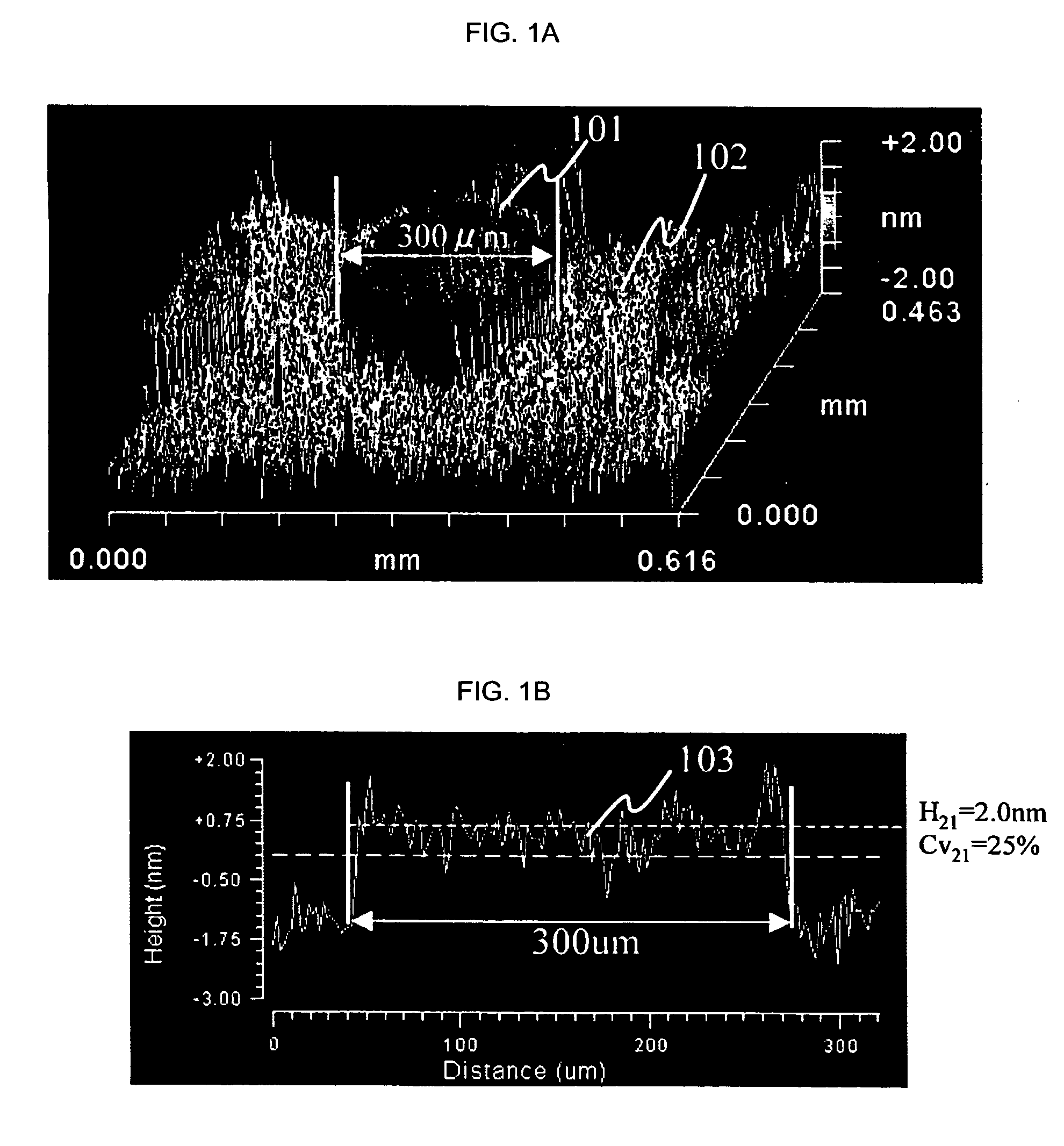
[0036] A plane type DNA microarray was produced according to a producing method as disclosed in the Japanese Patent laid-open publication No. 2004-28953. Borosilicate glass of a slide glass size was employed as a substrate, and on this substrate, 10,000 types of 50-mer probe DNA were spotted. The diameter of one spot size is around 300 μm, and each probe DNA was immobilized on the substrate on a monolayer level.

[0037] This DNA microarray was mounted on an XYZθ stage and immediately below a 10× objective lens. At this timing, the magnification of the lens may be any between 2.5× to 100×. Next, the surface of the microarray is irradiated with a white light from a halogen lamp almost perpendicularly. Then, the reflected light from the top surface of the microarray is al...


PUM


Abstract

When a biomolecule and a biochemical reactant are detected, a white interference method is used to conduct a noncontact and nondestructive detection, and further to conduct efficient and accurate detection. This method is applied to a biosensor element, whereby non-labeled and noncontact quality control can be achieved.

Description

BACKGROUND OF THE INVENTION [0001] The present invention relates to a method for nondestructive / noncontact testing of a biosensor element on the surface of which a nucleic acid, protein, and the like are immobilized for sensing of biomolecules and chemical reactions, and a method for manufacturing this biosensor element. [0002] The human genome sequence has been entirely deciphered by the human genome project, and currently a subject matter of the study is shifting from the conventional “sequence analysis” to “functional analysis” that examines functions thereof. Data obtained from this functional analysis are considered to be able to provide significant information to elucidate life phenomena, and it is expected that such data may become a key to solve problems in every field associated with living things, such as medical practice, environment, and foods. [0003] In the functional analysis above, it is demanded that a gene having an enormous amount of information and a protein made ...

Claims


Application Information

Patent Timeline
IPC IPC(8): C12Q1/68G01N33/53C12M1/34G06F19/00G01B11/24G01N21/45G01N21/75
CPCG01B11/2441G01B11/0675
Inventor NAKAHARA, MIWAKOINOUE, TAKASHISAEKI, TOMONORIKOGI, OSAMUBAN, NORIKO
Owner HITACHI SOFTWARE ENG
Learn More