Multi-layer direct conversion computed tomography detector module

a detector module and computed tomography technology, applied in the field of diagnostic imaging radiography detectors, can solve the problems of detector saturation, type of detectors that cannot count at the x-ray photon flux rate typically encountered, and inability to provide data or feedback as to the number and/or energy of photons detected, etc., to achieve the effect of facilitating electron collection

Active Publication Date: 2007-01-04
GENERAL ELECTRIC CO
View PDF8 Cites 51 Cited by
  • Summary
  • Abstract
  • Description
  • Claims
  • Application Information

AI Technical Summary

Benefits of technology

[0013] In accordance with another aspect of the present technique a computed tomography detector module is presented. The detector module includes a substrate having a topside and a bottom side. Furthermore, the detector module includes a plurality of detector layers disposed on the top side of the substrate in a direction that is substantially orthogonal to the substrate, where each of the plurality of detector layers comprises a direct conversion material configured to absorb radiation, and where each of the plurality of detector layers comprises a first side and a second side. The detector module also includes a plurality of pixelated anode contacts disposed on the first side of each of the plurality of detector layers, where the plurality of pixelated anode contacts comprises anode contacts of substantially equal size. Additionally, the detector module includes a common cathode contact disposed on the second side of each of the plurality of detector layers. The detector module also includes a non-collecting, control grid structure disposed between each of the plurality of pixelated anode contacts, where the control grid structure is configured to facilitate collection of electrons at the plurality of pixelated anode contacts.
[0014] In accordance with further aspects o

Problems solved by technology

A drawback of such detectors however is their inability to provide data or feedback as to the number and/or energy of photons detected.
However, a drawback of these direct conversion semiconductor detectors is that these types of detectors cannot count at the x-ray photon flux rates typically encountered with conventional CT systems.
Further, the very high x-ray photon flux rate has been known to cause pile-up and polarization that ultimately leads to detector saturation.
Above these thresholds, the detector response is not predictable or has degraded dose utilization.
Further, as will be appreciated, detector saturation leads to loss of imaging information and consequently results in artifacts in x-ray projection and CT images.
In addition, hysteresis and other non-linear effects occur at flux levels near detector saturation as well as flux levels over detector saturation.
As previously noted, direct conversion detectors are also susceptible to a phenomenon called “polarization” where charge trapping inside the material changes the local electric field, alters the detector count and energy response in an unpredictable way, and results in hysteresis where response is altered by previous exposure history.
Incomplete collection of x-rays results in reduced image quality, i.e., a noisy image.
In addition, detectors that measure x-ray photon count rate and energy are subject to a count rate saturation limit.
Thin detectors allow for rapid charge collection, but they do not have sufficient stopping power to capture the x-rays efficiently when the x-rays are incident along the thin dimension.
However, this leads to large charge collection time and associated low flux rate saturation limits.
Another disadvantage of thick layer detectors is that charge trapping is more likely during transport through a thick layer.
Trapped charge changes the internal electric field and consequently alters the detector gain and spectral response.
X-rays that are collected near a boundary between two pixels are shared between these pixels leading to miscounting of the number of incident photons, or incorrect registration of the photon energy.
Thick layers are also difficult to create by a deposition technique.
During this charge transport, crosstalk and charge trapping

Method used


Image

  • Multi-layer direct conversion computed tomography detector module
  • Multi-layer direct conversion computed tomography detector module
  • Multi-layer direct conversion computed tomography detector module

Examples


Embodiment Construction

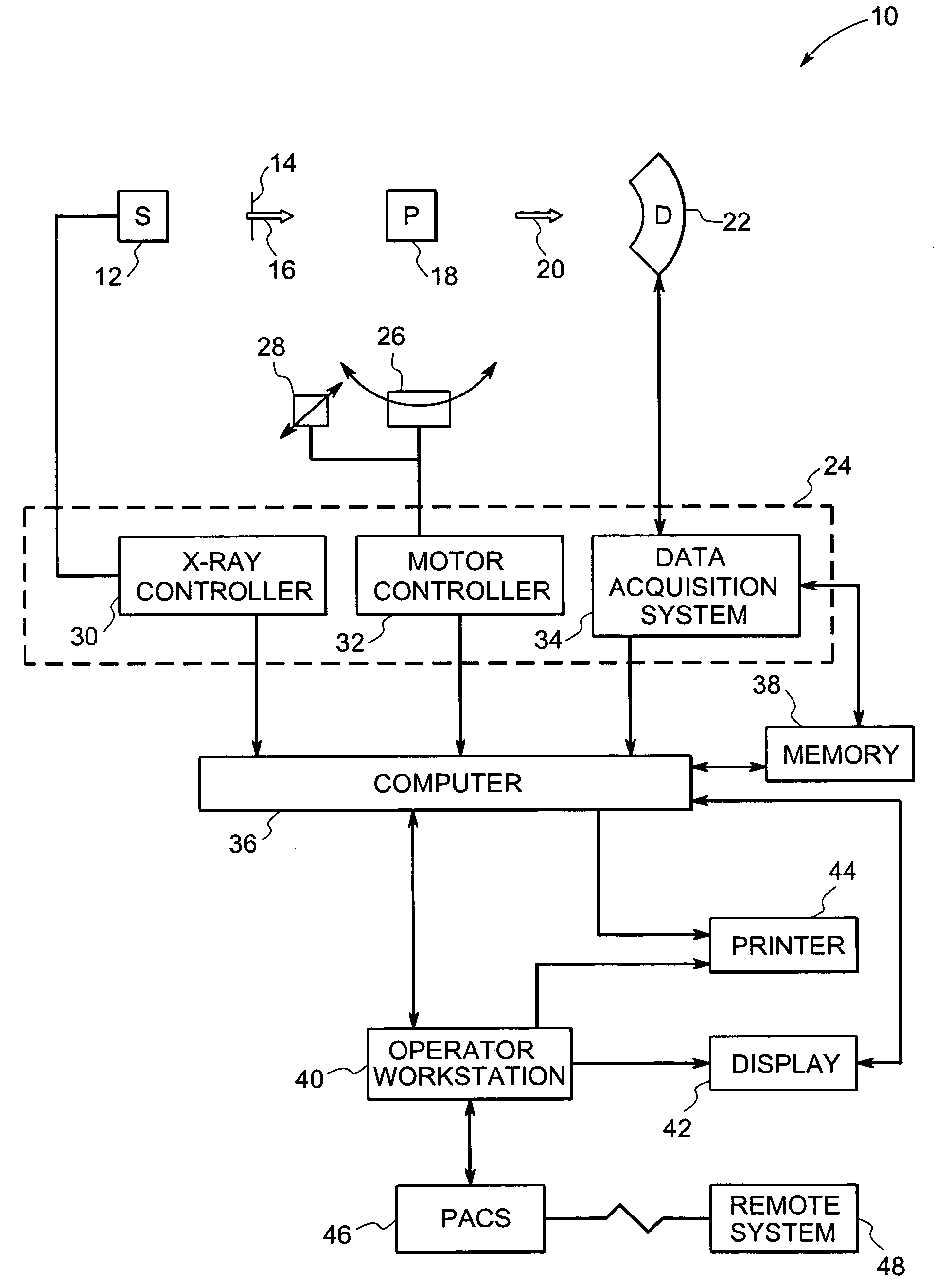
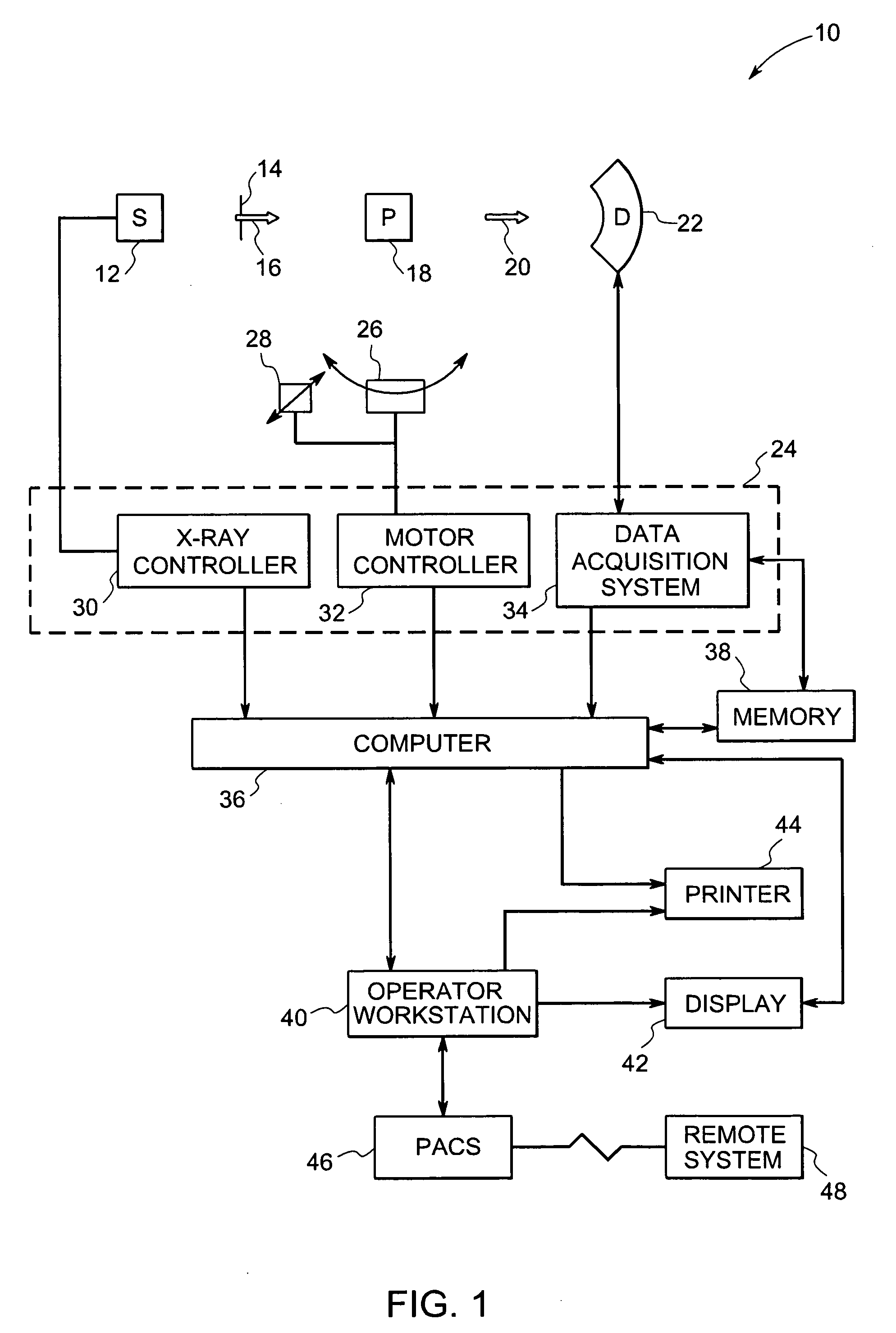
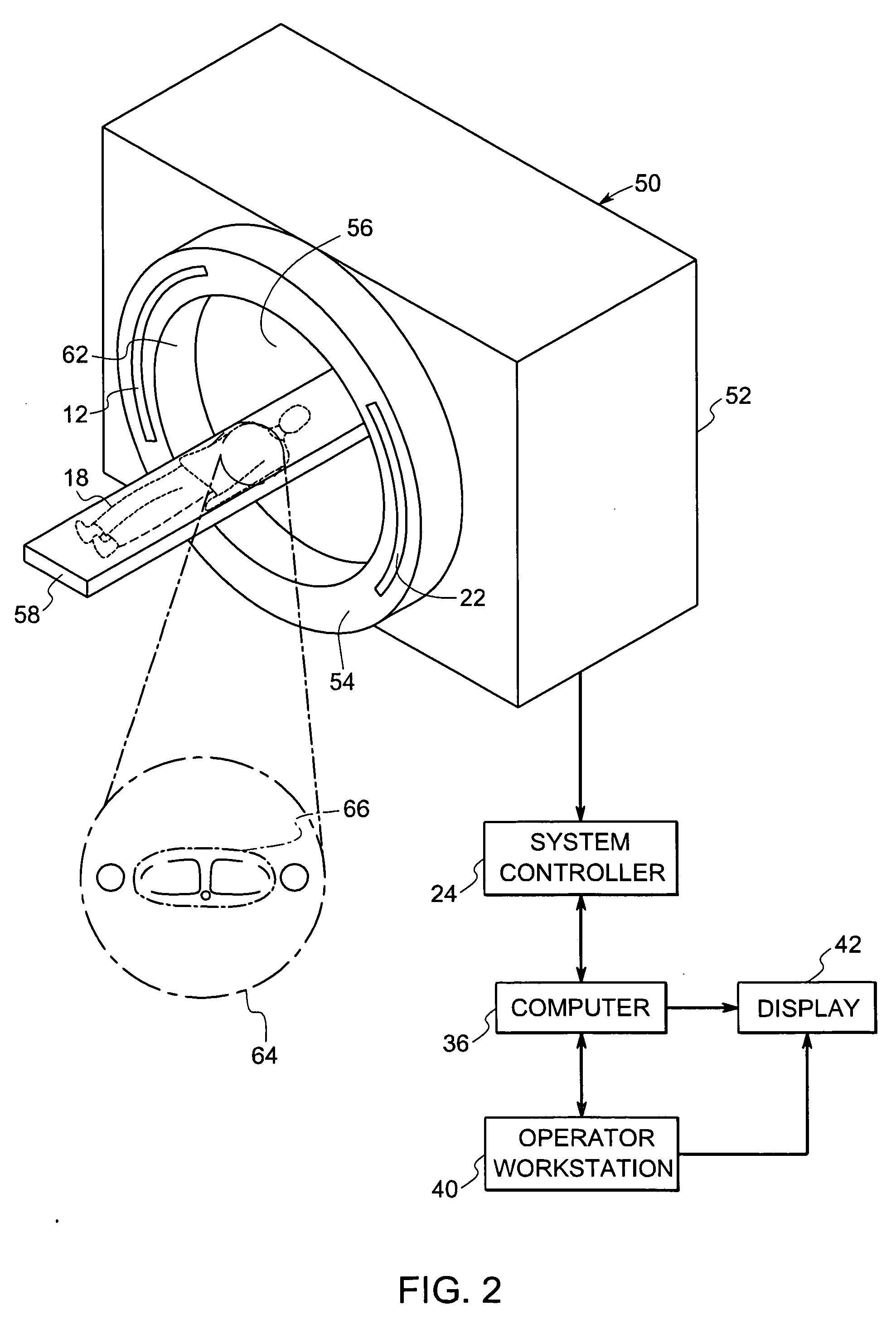
[0037] Conventional CT imaging systems utilize detectors that convert radiographic energy into current signals that are integrated over a time period, then measured and ultimately digitized. A drawback of such detectors however is their inability to provide data or feedback as to the number and / or energy of photons detected. Further, energy discriminating, direct conversion detectors are capable of not only x-ray counting, but also providing a measurement of the energy level of each x-ray detected. However, a drawback of these direct conversion semiconductor detectors is that these types of detectors cannot count at the x-ray photon flux rates typically encountered with conventional CT systems. Further, the very high x-ray photon flux rate has been known to cause pile-up and polarization that ultimately leads to detector saturation. In other words, these detectors typically saturate at relatively low x-ray flux level thresholds. It would therefore be desirable to develop a direct co...


PUM


Abstract

A computed tomography detector module is presented. The detector module includes a substrate having a topside and a bottom side. Additionally, the detector module includes a plurality of detector layers disposed on the top side of the substrate in a direction that is substantially orthogonal to the substrate, where each of the plurality of detector layers comprises a direct conversion material configured to absorb radiation, and where each of the plurality of detector layers comprises a first side and a second side. Further, the detector module includes a plurality of pixelated anode contacts is disposed on the first side of each of the plurality of detector layers. Also, the detector module includes a common cathode contact is disposed on the second side of each of the plurality of detector layers.

Description

BACKGROUND [0001] The invention relates generally to radiographic detectors for diagnostic imaging, and more particularly to a multi-layer, direct conversion computed tomography (CT) detector for high flux rate imaging with photon counting and energy discrimination. [0002] Radiographic imaging systems, such as x-ray and computed tomography (CT) have been employed for observing, in real time, interior aspects of an object. Typically, the imaging systems include an x-ray source that is configured to emit x-rays toward an object of interest, such as a patient or a piece of luggage. A detecting device, such as an array of radiation detectors, is positioned on the other side of the object and is configured to detect the x-rays transmitted through the object. As will be appreciated, the intensity of the attenuated beam radiation received at the array of detectors is typically dependent upon the attenuation of the x-rays by the object. Each detector element of the array of detectors is con...

Claims


Application Information

Patent Timeline
IPC IPC(8): H05G1/60A61B6/00G01N23/00G21K1/12
CPCG01T1/2985G01T1/241G01T1/249G01T1/243G01T1/242
Inventor TKACZYK, JOHN ERICLEBLANC, JAMES WALTERLI, WENWALTER, DEBORAH JOYDU, YANFENG
Owner GENERAL ELECTRIC CO
Why Eureka
Try Eureka