
Backlight unit and liquid crystal display device using the same

a backlight unit and liquid crystal display technology, applied in non-linear optics, instruments, optics, etc., can solve the problems of deteriorating the display quality and affecting the operation of the liquid crystal display device. , to prevent the deformation of the flat surface, the effect of preventing the abrasion of the optical surfa

Active Publication Date: 2007-01-04
LG DISPLAY CO LTD
View PDF2 Cites 7 Cited by
  • Summary
  • Abstract
  • Description
  • Claims
  • Application Information

AI Technical Summary

Benefits of technology

[0019] An advantage of the present invention is to provide a backlight unit of a liquid crystal display device that is adaptive for preventing abrasion of surfaces of optical sheets caused because the optical sheets freely move and preventing deformation of the flat surface of the optical sheets.

Problems solved by technology

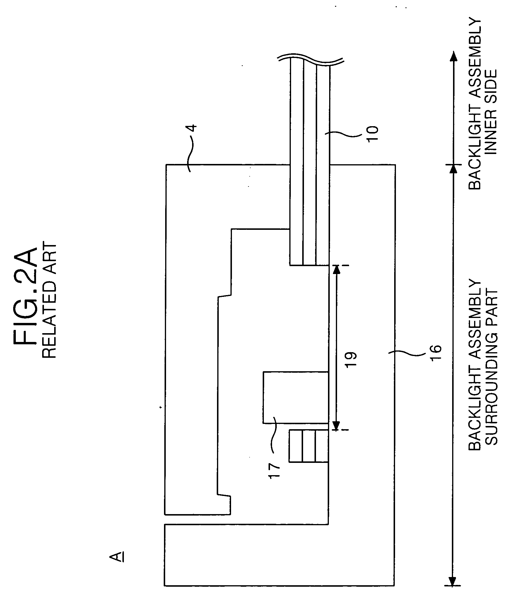
Friction generated by the relative motion of individual optical sheets can result in the surface of the optical sheets being worn away and a prism on a prism sheet for controlling the path of light might be damaged.
The above described problems can result in deterioration of a display quality of the liquid crystal display device.

Method used


Image

  • Backlight unit and liquid crystal display device using the same
  • Backlight unit and liquid crystal display device using the same
  • Backlight unit and liquid crystal display device using the same

Examples


first embodiment

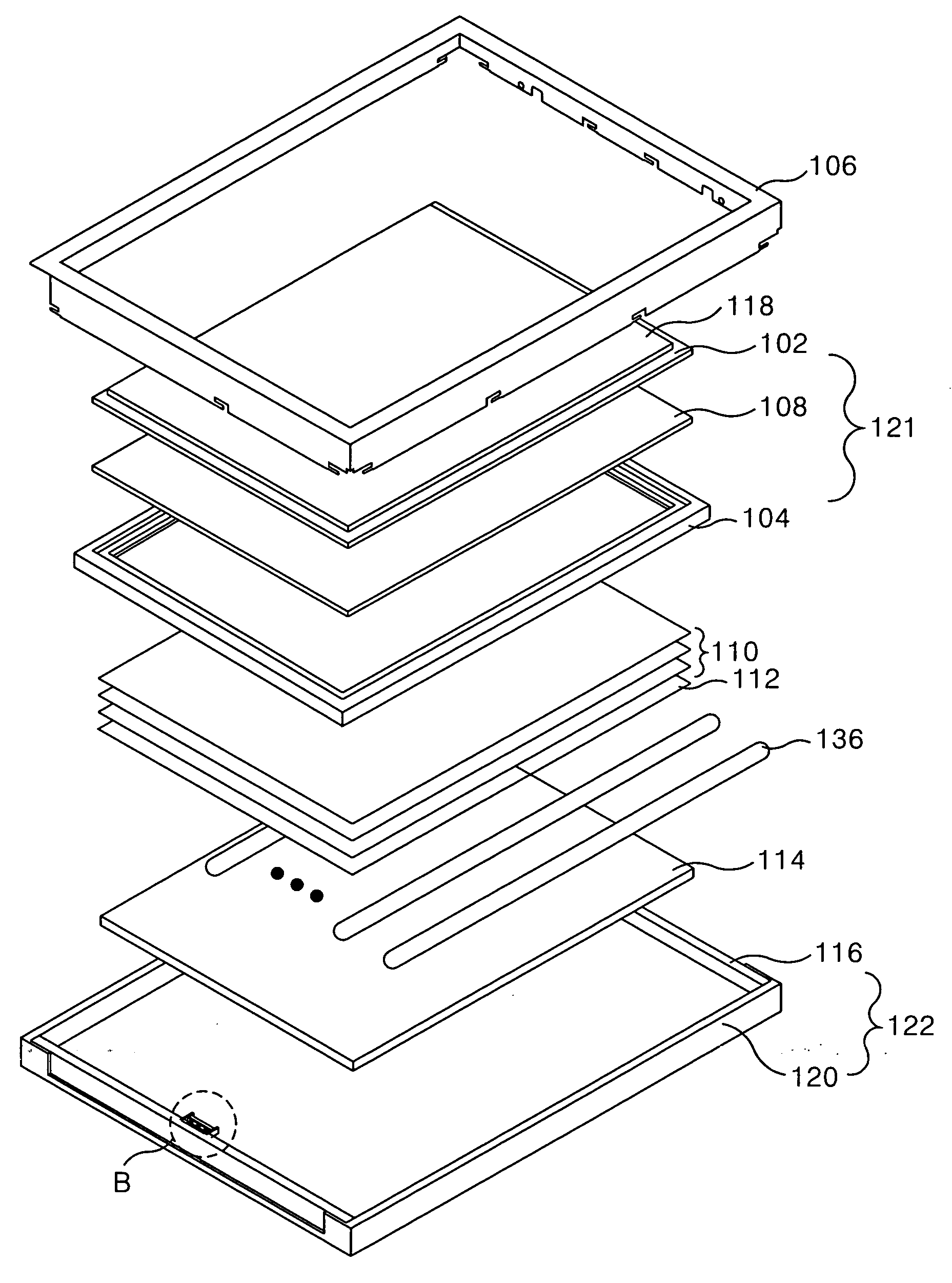
[0033]FIG. 3 is a diagram representing a liquid crystal display module according to the present invention.

[0034] Referring to FIG. 3, the liquid crystal display module according to an embodiment of the present invention includes a board assembly 121 inclusive of a liquid crystal display panel 102 and polarizing sheets 108 and 118 formed on front and rear surfaces of the liquid crystal display panel 102; a backlight unit which receives power from an external power source to irradiate light onto the liquid crystal display panel 102; a guide panel 104 installed between the liquid crystal display panel 102 and the backlight unit to support the liquid crystal display panel 102 and to be joined with the side surface of a support side bottom 116.

[0035] The liquid crystal display panel 102 includes liquid crystal cells arranged in a matrix between upper and lower glass substrates and a thin film transistor (hereinafter, referred to as ‘TFT’) is installed at each liquid crystal cell for swi...

second embodiment

[0051]FIGS. 5A and 5B illustrate a joining part according to the present invention.

[0052] Referring to FIGS. 5A and 5B, in a liquid crystal display module according to a second embodiment of the present invention, a joining part of a support side bottom 136 for combining the optical sheets 130 includes an elastic body 121 connected to a side wall 126b of the support main 136; and a rotatable body 123 movable in a horizontal movement direction against an elastic body 121. The elastic body 121 of the joining part according to the second embodiment of the present invention is a plate spring. The plate spring 121 is formed of a material having a relatively small the modulus of elasticity allowing the plate spring to be deformed with a little force. For example, a thin metal or plastic film can be used as the plate spring 121.

[0053] A supporting member 127 of a cylindrical or a polygonal prism shape is formed at the end of the plate spring. The supporting member 127 is constrained to mo...


PUM

PropertyMeasurementUnit
elasticaaaaaaaaaa
shapeaaaaaaaaaa
moving distanceaaaaaaaaaa

Abstract

A backlight unit that for preventing an optical sheet from moving freely and preventing deterioration of picture quality caused by deformation. The backlight unit of a liquid crystal display device includes a light source; a reflecting sheet disposed in a rear surface of the light source; an optical sheet to direct light emitted from the light source to travel in a direction towards a liquid crystal display panel; and a cover bottom assembly formed to house the light source, the reflection sheet and the optical sheet. The cover bottom assembly comprises support side bottoms formed at two short sides of the cover bottom assembly to dispose the optical sheet thereon, and the support side bottom includes a joining part to fix the optical sheet to the support side bottom using a movable body movable on a surface of the optical sheet.

Description

[0001] This application claims the benefit of Korean Patent Application No. P2005-0058854, filed on Jun. 30, 2005, which is hereby incorporated by reference for all purposes as if fully set forth herein. BACKGROUND OF THE INVENTION [0002] 1. Field of the Invention [0003] The present invention relates to a liquid crystal display device, and more particularly to a backlight unit for preventing abrasion of a surface of an optical sheet. [0004] 2. Discussion of the Related Art [0005] A liquid crystal display device (hereinafter, referred to as ‘LCD’) is a flat panel display device that displays a picture by controlling the transmittance of light according to a video signal. Because LCDs are light in weight, thin, and have low power consumption, LCDs are used in an increasing number of applications. LCDs are used as the display devices for equipment such as notebook computers and office automation equipment. The LCD is being actively developed to produce displays having larger screens, h...

Claims


Application Information

Patent Timeline
Patent Type & Authority Applications(United States)
IPC IPC(8): G02F1/1333
CPCG02F2201/54G02F1/133608G02F1/1335
Inventor KIM, GI BINKIM, TAE WOO
Owner LG DISPLAY CO LTD
Learn More