Antitheft device

Inactive Publication Date: 2014-08-28
LINTEX
View PDF8 Cites 1 Cited by
  • Summary
  • Abstract
  • Description
  • Claims
  • Application Information

AI Technical Summary

Benefits of technology

The present invention provides an antitheft device that can be used on objects without locking holes to prevent surface abrasion. The device includes a cover and a base plate with adhesive elements for securely attaching the device to an object. The cover has a top plate and flange that forms a locking mechanism with the base plate for easy positioning. The adhesive element is protected from exposure and not easily broken, ensuring better security. The device prevents theft of objects and prevents damage to the object's surface.

Problems solved by technology

Thus, the antitheft device may not be utilized on products without corresponding locking holes, such as printers, monitors, or cell phones.
However, surface of the products may be abraded by the string.
On the other hand, the string adhered onto the products is unable to be utilized repeatedly, and adhesive may remain on the surface of the products.
Furthermore, to facilitate detaching, the adhesive layer is usually exposed outside, so the adhesive layer is easier to be broken so that the antitheft device hardly secures the products.

Method used


Image

  • Antitheft device
  • Antitheft device
  • Antitheft device

Examples


first embodiment

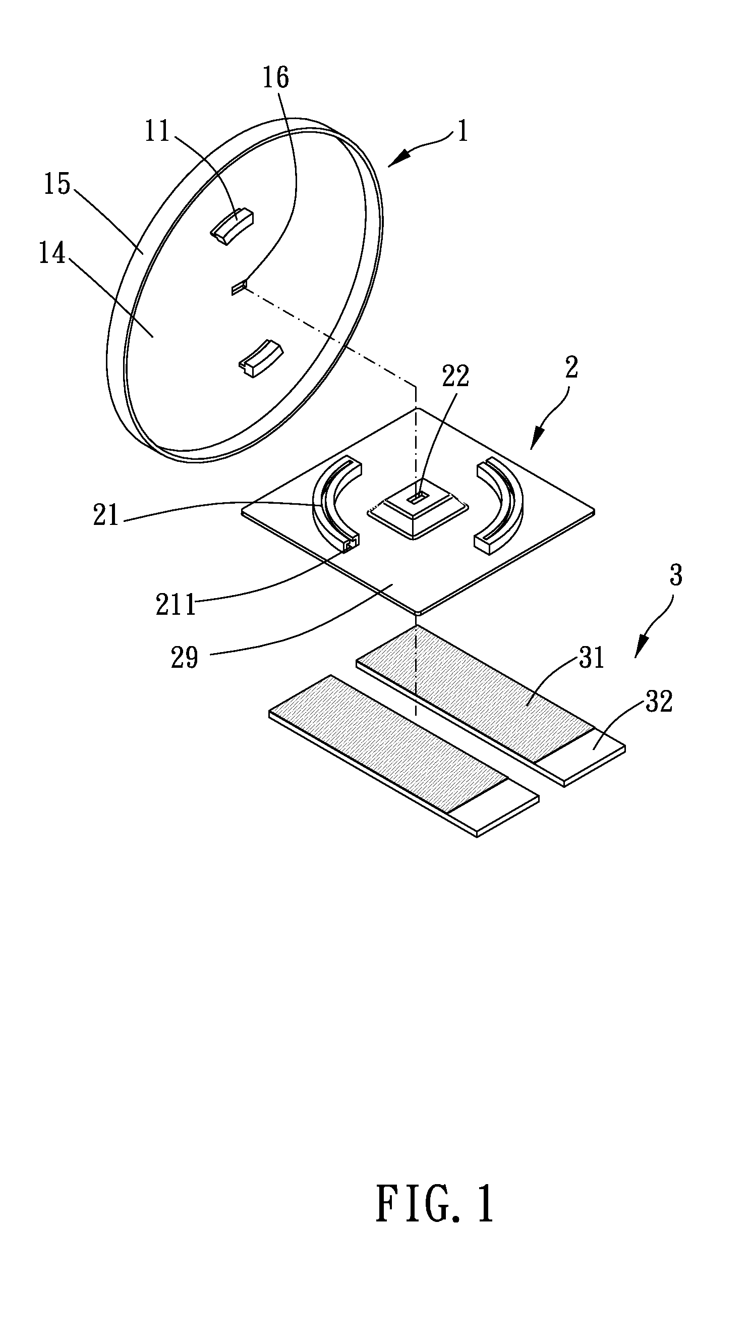
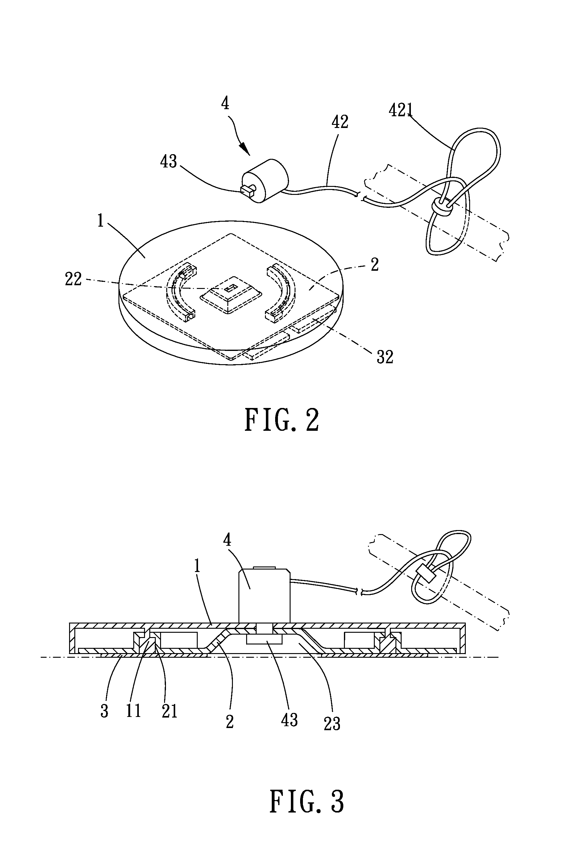
[0025]Please refer to FIG. 1 to FIG. 3 for the present invention. The antitheft device of the present embodiment includes a cover 1, a base plate 2, an adhesive element 3, and a controlling element 4.

[0026]The cover 1 includes a top plate 14 and a flange 15 extending from a periphery of the top plate 14 toward the base plate 2. A receiving space is enclosed and defined by the top plate 14 and the flange 15. The top plate 14 forms a first engaging portion and a hollow portion 16. The first engaging portion protrudes from the top plate 14 toward the base plate 2. The first engaging portion includes two T-shaped tracks 11. Each T-shaped track 11 has a T-shaped cross-section, and the two T-shaped tracks 11 are arranged symmetrically at two opposite ends of the top plate 14. A longitudinal direction of each T-shaped track 11 is annular. The hollow portion 16 is a square hole.

[0027]The base plate 2 is located in the receiving space and has a bottom face and a top face 29. The top face 29 ...

second embodiment

[0033]Please refer to FIGS. 4 to 6 for the present invention. Longitudinal directions of the T-shaped track 12 and the elongated slot 24 are linear. Thus, the cover is able to move with respect to the base plate along a linear direction.

third embodiment

[0034]Please refer to FIGS. 7 to 9 for the present invention. The first engaging portion includes two abutting portions 13 arranged at two opposite ends of the cover 1. The cover 1 is slightly deformable. The second engaging portion includes two buckle portions 25 arranged at two opposite ends of the base plate 2. The abutting portions 13 positionally correspond to the buckle portions 25 so that the cover 1 is able to be positioned to the base plate 2, as shown in FIG. 8. To separate the abutting portions 13 from the buckle portions 25, a user can squeeze the cover 1 for deforming so that the abutting portions 25 move away from the buckle portions 25, as shown in FIG. 9. Thereby, the cover 1 is able to be removed from the base plate 2. Specifically, the abutting portions 13 form inclined faces 131. When the cover 1 is to be disposed to the base plate 2, the buckle portions 25 abut against the inclined faces 131 and push it away so that the buckle portions 25 are not restricted by th...


PUM


Abstract

An antitheft device includes a cover, a base plate, and an adhesive element. The base plate is located in a receiving space of the cover and is adapted for a controlling element to connect thereto to release or lock the cover and the base plate. The base plate is able to be adhered onto an object to be secured by the adhesive element. The adhesive element is also located in the receiving space of the cover so that the adhesive element is prevented from being removed or broken easily.

Description

BACKGROUND OF THE INVENTION[0001]1. Field of the Invention[0002]The present invention relates to an antitheft device adapted for securing an object from being stolen.[0003]2. Description of the Prior Art[0004]A conventional antitheft device for securing a computer comprises a lock and a string. The string is connected with the lock and is able to be sleeved around a fixed object, such as a table leg. Thereafter, the lock is positioned to a notebook computer so that the notebook computer is secured near the table leg from being stolen.[0005]However, the notebook computer to be secured must form a locking hole having a shape corresponding to the lock. Thus, the antitheft device may not be utilized on products without corresponding locking holes, such as printers, monitors, or cell phones. To secure products without locking holes, string is usually used to wrap or tie the products or to be adhered onto the products. However, surface of the products may be abraded by the string. On the ...

Claims


Application Information

Patent Timeline
IPC IPC(8): E05B73/00
CPCE05B73/0082E05B73/0005
Inventor LIN, CHIA-SHENG
Owner LINTEX
Why Eureka
Try Eureka