Adjustable camshaft

A camshaft, adjustable technology, applied in the direction of valve device, machine/engine, mechanical equipment, etc., can solve problems such as high cost and disadvantage

Active Publication Date: 2016-02-17
THYSSENKRUPP PRESTA TECCENTER AG
View PDF7 Cites 2 Cited by
  • Summary
  • Abstract
  • Description
  • Claims
  • Application Information

AI Technical Summary

Problems solved by technology

Here, the oil retention hole is provided in the cam element, which is disadvantageous during machining
In particular, the cost of introducing oil guide grooves in the inner surface of the cam hole of the cam element is high, and it is obvious that a large amount of lubricating oil remains in the oil guide grooves due to the centrifugal force during the rotation of the camshaft Therefore, it is desired to improve the passage of lubricating oil from the oil guide groove to the sliding bearing gap

Method used


Image

  • Adjustable camshaft
  • Adjustable camshaft
  • Adjustable camshaft

Examples


Embodiment Construction

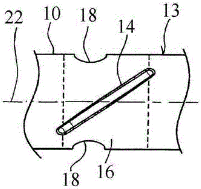
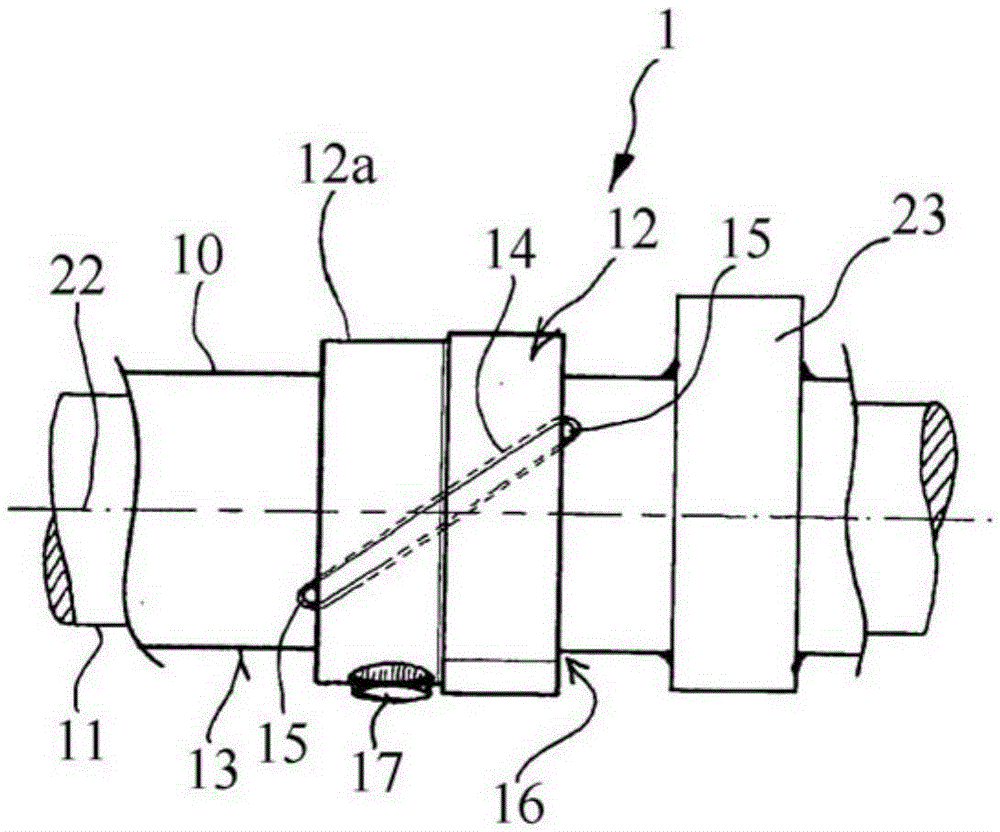
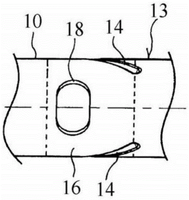
[0050] figure 1 and figure 2 A first exemplary embodiment of an adjustable camshaft 1 is shown, figure 1 shows the details of the outer axis 10, while figure 2 shows the basis for figure 1 Detail of the outer shaft 10 of the camshaft 1. The outer shaft 10 is formed in the form of a hollow shaft, through which the inner shaft 11 extends and is rotatable independently of the outer shaft 10 about a common camshaft axis 22 . Here, the inner shaft 11 is rotatably supported in the outer shaft 10 . The cam element 23 is rigidly mounted on the outer shaft 10, and the cam element 23 may for example be welded to the outer shaft 10 or fixed on the enlarged diameter by press fitting. Therefore, the cam member 23 rotates in phase with the outer shaft 10 .

[0051] In the region of the joint 16 a further cam element 12 is mounted rotatably on the outer surface 13 of the outer shaft 10 so as to form a slide bearing play. The cam element 12 includes a cam flange 12a, and the cam elem...


PUM


Abstract

The invention relates to an adjustable camshaft (1) for the valve train of an internal combustion engine, having an outer shaft (10) and an inner shaft (11) extending concentrically with the outer shaft (10) and rotatably accommodated therein, wherein on the outer surface (13) of the outer shaft (10), at least one cam member (12) is rotatably mounted while forming a slide bearing gap, wherein the cam member (12) is connected to the inner shaft (11) in a rotationally fixedly manner. According to the invention, in the outer surface (13) of the outer shaft (10), at least one oil routing groove (14) is introduced in a position and with an axial length such that the oil routing groove (14) is formed at least across the axial width of the slide bearing gap, and that on at least one side of the cam member (12), the oil routing groove is brought out from the slide bearing gap with a free groove portion (15).

Description

technical field [0001] The invention relates to a camshaft for a valve train of an internal combustion engine, said camshaft having an outer shaft and an inner shaft extending concentrically in the outer shaft and being rotatably mounted in the outer shaft, wherein at least one cam element Rotatably supported on an outer surface of the outer shaft forming a slide bearing gap, and wherein the cam element is fixedly rotatably connected to the inner shaft. Background technique [0002] Adjustable camshaft for a valve train of an internal combustion engine for variable control of intake and exhaust valves of an internal combustion engine, said camshaft having an outer shaft on which cam elements are mounted and arranged in a fixed Rotationally connected to an inner shaft that extends through the outer shaft. The other cam elements are fixedly rotatably mounted on the outer shaft, and if the phase of the inner shaft is adjusted with respect to the phase of the outer shaft, the p...

Claims


Application Information

Patent Timeline
Patent Type & Authority Applications(China)
IPC IPC(8): F01L1/047
CPCF01L1/047F01L2001/0473F01L2810/02
Inventor B·曼U·迪特尔J·莫伊泽尔M·昆茨M·莱曼
Owner THYSSENKRUPP PRESTA TECCENTER AG
Why Eureka
Try Eureka