
Intra-subject position display system

Active Publication Date: 2007-01-04
OLYMPUS CORP
View PDF26 Cites 151 Cited by
  • Summary
  • Abstract
  • Description
  • Claims
  • Application Information

AI Technical Summary

Benefits of technology

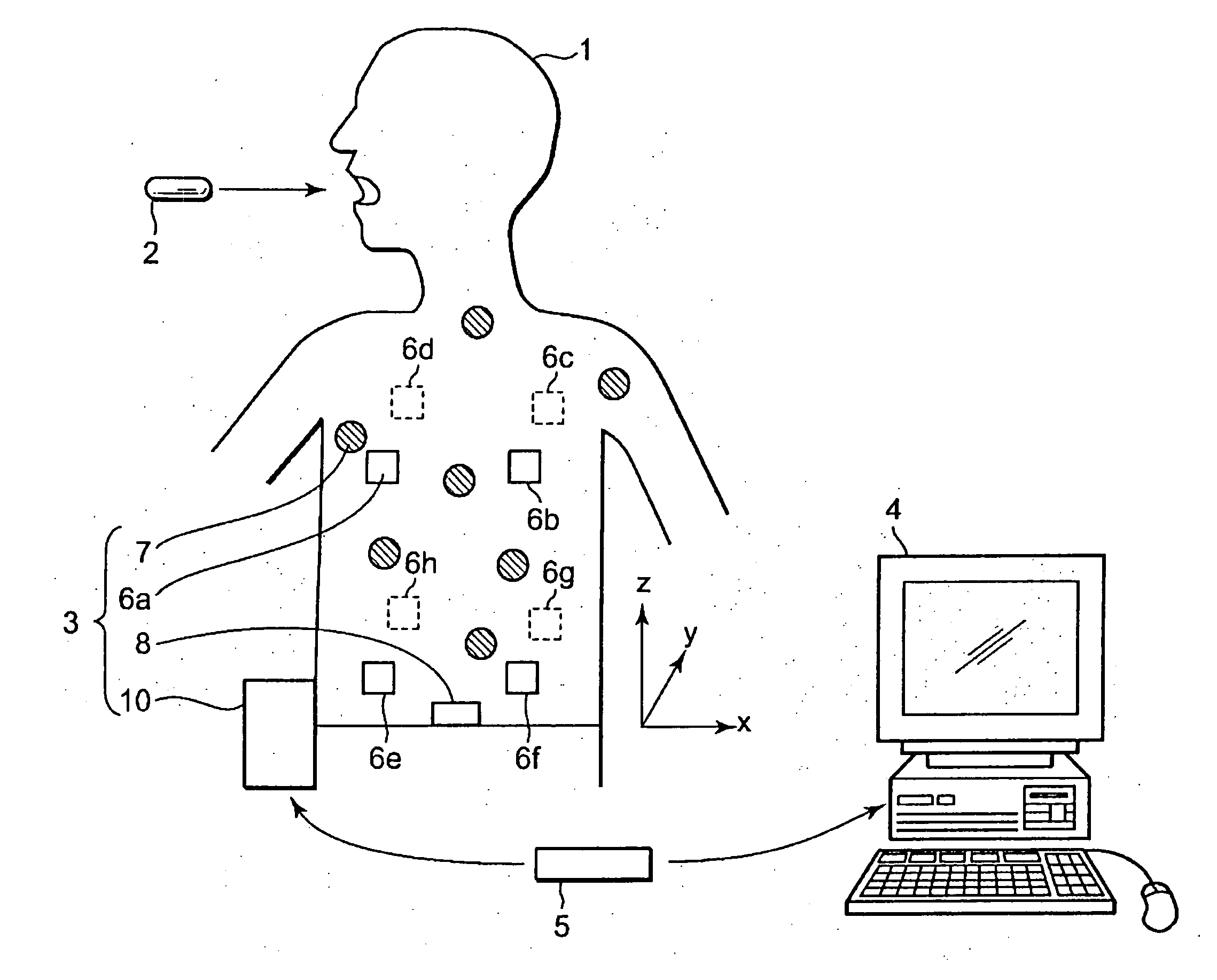
[0014] Thereby, an operator can see the position of the intra-subject device in a relation with the outer surface of the subject, by which the operator can easily understand the position of the intra-subject device in the subject.
[0019] In this example, the magnetic field sensor can be disposed in a fixed positional relation with at least one of the outer surface sensors. The positional relation deriving section derives the positional relation between the outer surface of the subject and the magnetic field sensor on the basis of the position of the outer surface sensor disposed in the fixed positional relation with the magnetic field sensor. Thereby, due to the fixed relative position of the magnetic field sensor and the outer surface sensor, calculations for deriving the positional relationship become easy.
[0029] The intra-subject position display system can comprise a display device for displaying a relative position of the intra-subject device in the subject in relation to the outer surface of the subject having individual variations. Therefore, an observer such as a doctor or nurse can realize a relative position with the outer surface of the subject having individual variations, instead of an absolute position of the intra-subject device. For example, if the present invention is applied to a capsule type endoscope, it is possible to easily estimate which organ the capsule type endoscope is passing through.

Problems solved by technology

In the conventional capsule endoscopic system, however, it is hard for a doctor, a nurse, or the like to understand the picked-up image's position in the subject.
When this arrangement is adopted, however, it is possible to detect the position of the capsule type endoscope in relation to the receiver, but it is hard to detect a relative position of the capsule type endoscope in the subject.
If only the position of the capsule type endoscope relative to the receiver (so to speak, an absolute position) is derived, it is hard for a doctor or nurse to realize where the capsule type endoscope locates within the subject based on the absolute position.
Therefore, it is hard to determine in which organ of the subject the capsule type endoscope positions at a given time.
In some cases, such a system does not fully contribute to improve a convenience on a diagnosis or the like.

Method used


Image

  • Intra-subject position display system
  • Intra-subject position display system
  • Intra-subject position display system

Examples


first embodiment

[0047] The test capsule 2 is a target of measurement with the intra-subject position display system and functions as an intra-subject device. The test capsule 2 is for use in conducting a preliminary examination to check whether there is a narrow area or the like where a capsule type endoscope is hard to pass through in the subject 1 before introducing the capsule type endoscope or the like into the subject 1. The intra-subject position display system has a function of clearly displaying a position of the test capsule 2 in the subject in a relation with the subject 1. By this function, an observer can easily understand where the test capsule 2 is located in the inside of the subject 1, independently of individual variations of the subject 1: For example, which organ the test capsule 2 is passing through at a given time.

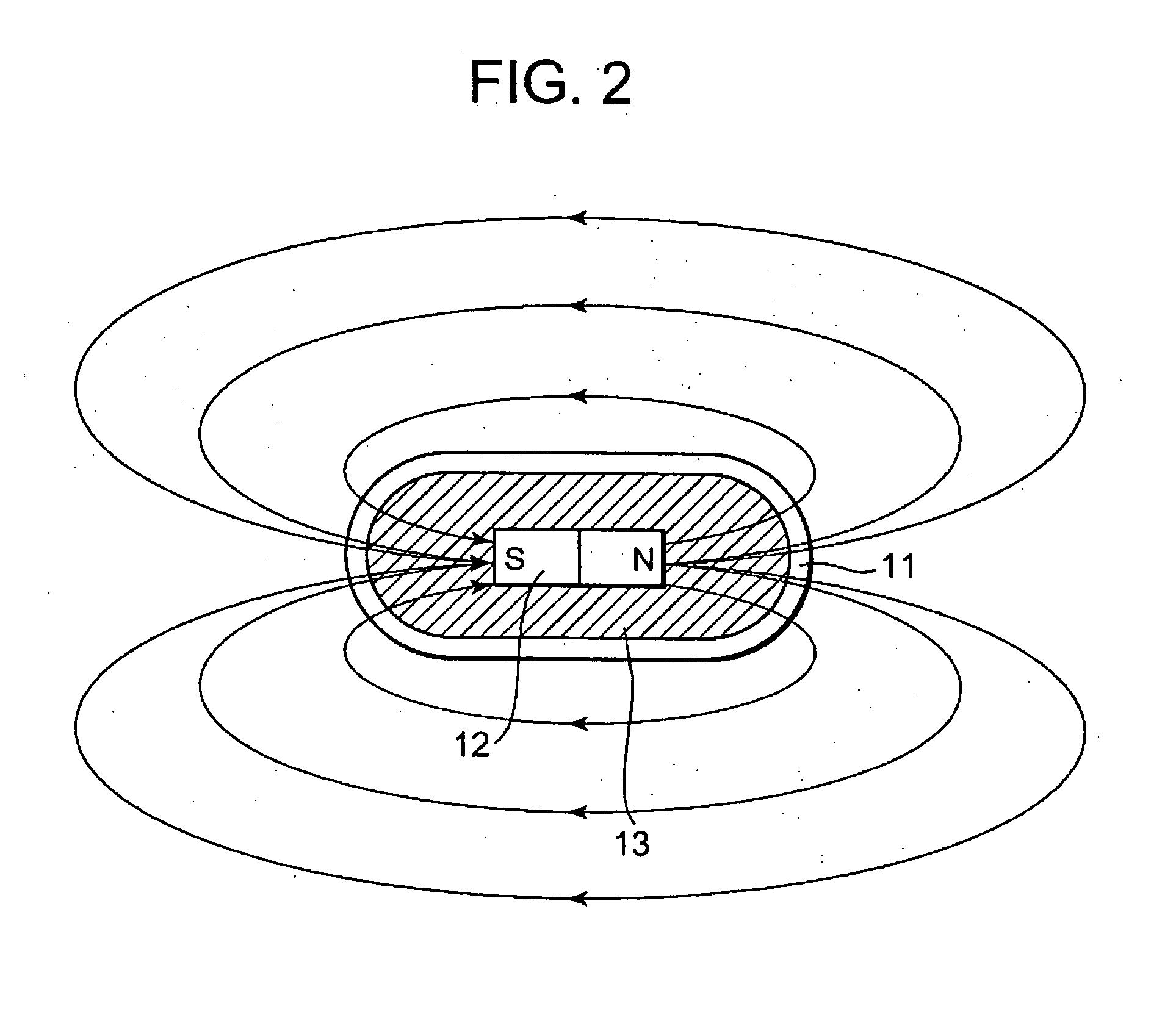
[0048]FIG. 2 is a schematic view showing a structure of the test capsule 2. As shown in FIG. 2, the test capsule 2 has a container 11 having the shape of a capsule s...

second embodiment

[0092] Referring to FIG. 10, there is shown a schematic view of a specific configuration of the outer surface sensor section and the outer surface information deriving device included in the intra-subject position display system according to the As shown in FIG. 10, the outer surface sensor section 40 includes an RFID tag 41 as a second radio section. The RFID tag 41 specifically includes a control section 43 connected to a loop antenna 42 and a storing section 44 having a function of outputting at least storage information to the control section 43 on the basis of an instruction from the control section 43.

[0093] The loop antenna 42 is for use in receiving a radio signal transmitted from the side of the outer surface information deriving device and including a control signal and a power supply signal. Specifically, the loop antenna 42 has a function of receiving the radio signal transmitted from the side of the outer surface information deriving device 45 and outputting it to the ...

third embodiment

[0100] With deriving the position of the outer surface sensor 7 in this mode, the intra-subject position display system can derive the position of the outer surface sensor 7 without a correspondence database. Moreover, the reference outer surface information deriving device 52 has a function of deriving a position on the basis of only radio signals received by the plurality of receiving antennas 53a to 53c without a correspondence previously derived in a stereotyped manner. Therefore, it can derive the position of the outer surface sensor 7 more accurately in response to individual variations or the like of the operation of the subject 1. As a result, the intra-subject position display system has an advantage of being capable of deriving the relative position of the test capsule 2 with a high accuracy.

[0101] Subsequently, an intra-subject position display system according to a fourth embodiment will be described below. In the intra-subject position display system according to the f...


PUM


Abstract

An intra-subject position display system for displaying a position of an intra-subject device, which is introduced into a subject and moves therein, wherein a relative position of the intra-subject device to an outer surface of the subject is detected and displayed. The position of the intra-subject device is displayed in a relation with the outer surface of the subject. Thereby, it is possible to easily determine in which site of the subject the intra-subject device exists. The present invention is effective to recognize a position of, for example, a capsule type endoscope or a test capsule therefor in the subject (e.g., a human body). To recognize the outer surface of the subject, for example, a plurality of radio devices are arranged on the outer surface of the subject and their radio signals are analyzed.

Description

CROSS-REFERENCE TO RELATED APPLICATION [0001] This application is based upon and claims the benefit of priority from prior Japanese Patent Application No. 2004-113191, filed Apr. 7, 2004, the entire contents of which is incorporated herein by reference. BACKGROUND OF THE INVENTION [0002] 1. Field of the Invention [0003] The present invention relates to an intra-subject position display system for displaying a position of an intra-subject device, which is introduced into a subject and moves inside the subject. [0004] 2. Description of the Related Art [0005] Recently, in the field of endoscopy, there has been suggested a swalloable capsule type endoscope. The capsule type endoscope is provided with an imaging function and a radio communication function. The capsule type endoscope has a function of moving inside the body cavity (for example, inside a stomach, small intestine, or other organs) by the organ's peristaltic motion and taking images sequentially after being swallowed from th...

Claims


Application Information

Patent Timeline
IPC IPC(8): G06T15/00A61B5/07A61B1/00A61B1/05A61B5/06A61B6/12A61B8/12
CPCA61B1/041A61B5/06A61B6/12A61B5/065A61B5/073A61B5/061
Inventor SUZUKI, KATSUYASASAGAWA, KATSUYOSHIHONDA, TAKEMITSUHIRAKAWA, KATSUMIKIMOTO, SEIICHIRONAGASE, AYAKONAKATSUCHI, KAZUTAKA
Owner OLYMPUS CORP
Learn More