
Gravitational wave propulsion

a technology of gravitational waves and propulsion, applied in the direction of cosmonautic vehicles, machines/engines, nuclear engineering, etc., can solve the problems of incoherence, weakening, and not building up,

Inactive Publication Date: 2007-01-04
GRAVWAVE
View PDF36 Cites 6 Cited by
  • Summary
  • Abstract
  • Description
  • Claims
  • Application Information

AI Technical Summary

Benefits of technology

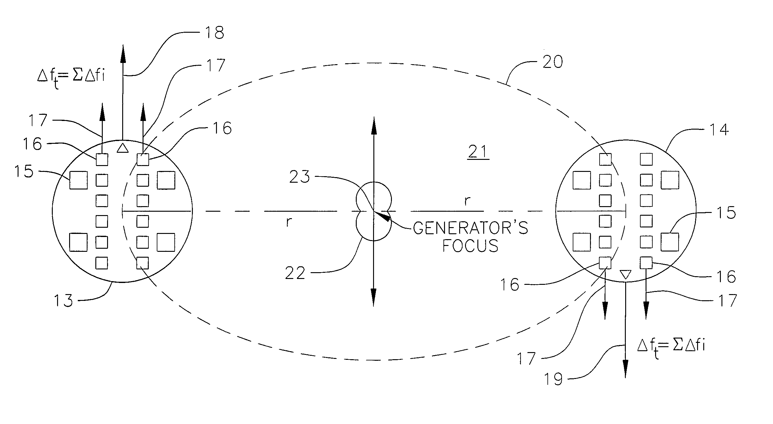
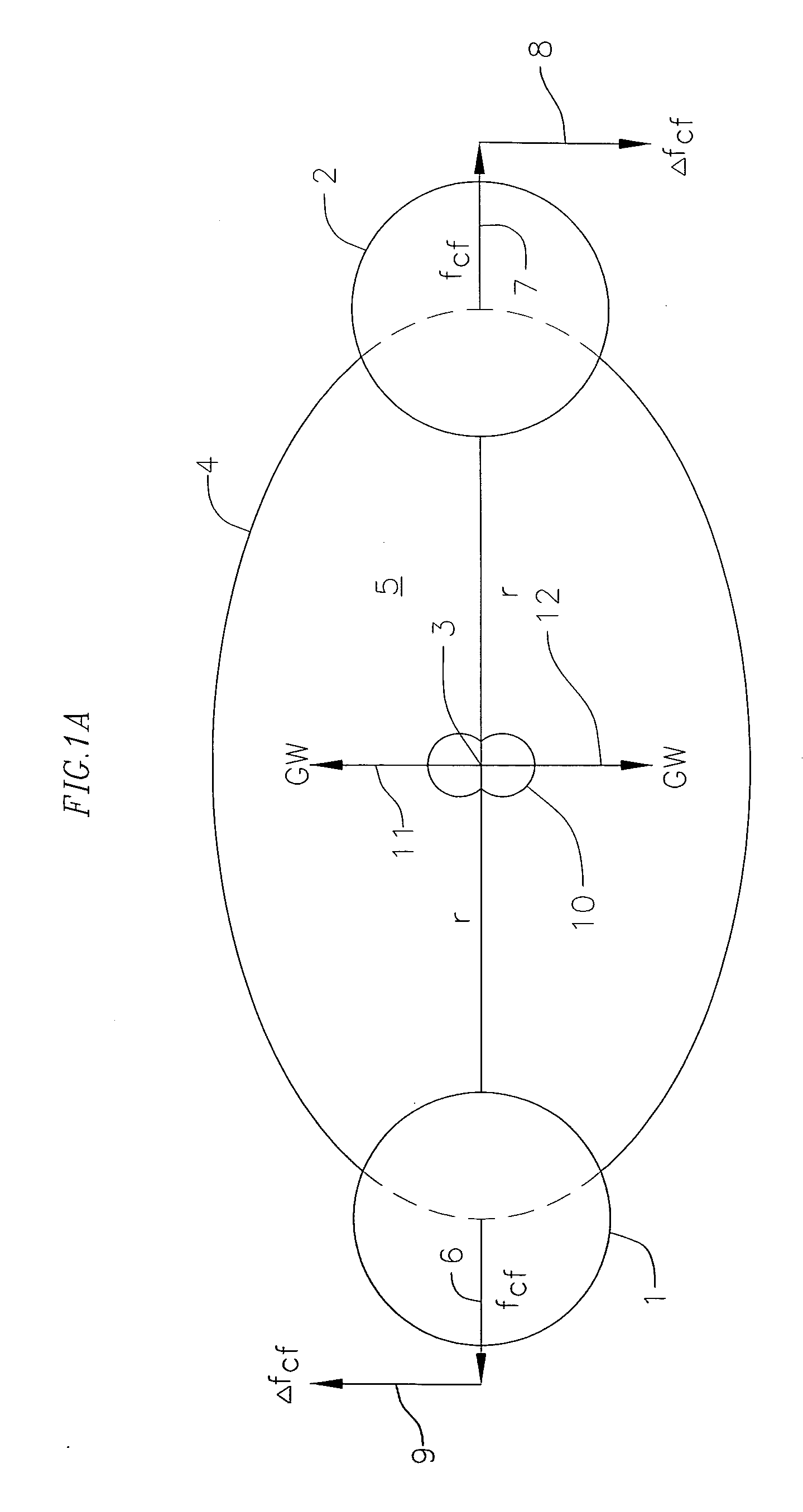
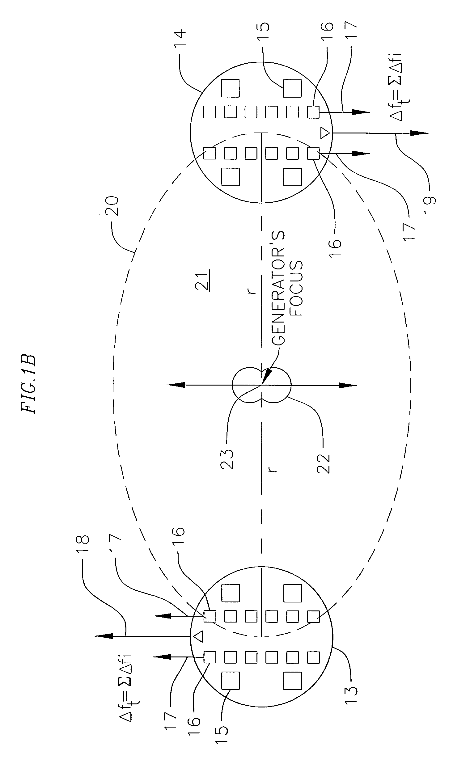
"The present invention is about generating gravitational waves using electromagnetic or nuclear forces. The invention involves using microwave emissions from commonly available magnetrons to energize piezoelectric crystals in ubiquitous FBARs. The FBARs are aligned in a dumbbell configuration to create GWs that emulate the change in centrifugal force created by two orbiting masses. The GWs generated have a frequency of twice the magnetron frequency and are directed towards the vehicle or assembly to be propelled. The GWs can be used to push the vehicle in the desired direction or change gravity along the path of the GW beam."

Problems solved by technology

In this case they are not coherent, do not build up and are much weaker than the GWs moving in the preferred direction.

Method used


Image

  • Gravitational wave propulsion
  • Gravitational wave propulsion
  • Gravitational wave propulsion

Examples


numerical example

[0024] As an illustrative example, the optimum arrangement is to have each 1 kW magnetron drive three 4″ FBAR wafers, assuming the rough estimates of costs given above. This excitation corresponds to ˜56 mW per FBAR, well within the power-handling capacity of this type of device (typically ˜2 W per FBAR is reported by Ruby, R., Bradley, P., Larson, J. D., and Oshmyansky, Y., “PCS 1900 MHz Duplexer Using Thin Film Bulk Acoustic Resonators (FBARs),”Elec. Lett., Volume 35, 794-795 (1999). Suppose that US$6M, an arbitrarily chosen sum, is available for the total hardware cost of the magnetrons and FBAR wafers. The optimum design at this price consists of 100,000 magnetrons, costing US$3M, driving a total of 300,000 FBAR wafers (total of 1.8×10⁹ FBARS), also costing US$3M The magnetrons are situated in clusters 600 m apart so that the radius of gyration, r, is 300 m, Laser surveying devices would be necessary to align all the energizable FBAR elements accurately towards the central focus...


PUM


Abstract

A gravitational wave generating device comprising an energizing means such as magnetrons, which act upon energizable elements such as film bulk acoustic resonators or FBARs. A computer that controls the magnetrons' phase. A gravitational wave generation device that exhibits directivity and forms a gravitational-wave beam. The utilization of a medium in which the gravitational wave speed is reduced in order to effect refraction of the gravitational wave and be a gravitational wave lens. A gravitational wave generator device that can be directed in order to propel an object by its momentum or by changing the gravitational field nearby the object to urge it in a preferred direction and be a propulsion means.

Description

REFERENCE TO RELATED APPLICATIONS [0001] This application is a continuation-in-part of application Ser. No. 10 / 738,142 filed Dec. 6, 2003, which is a continuation-in-part of application Ser. No. 09 / 752,975 filed Dec. 27, 2000, now U.S. Pat. No. 6,784,591, which is a continuation-in-part of application Ser. No. 09 / 616,683, filed Jul. 14, 2000, now U.S. Pat. No. 6,417,597, which is a continuation-in-part of application Ser. No. 09 / 443,527, filed Nov. 19, 1999, now U.S. Pat. No. 6,160,336.BACKGROUND OF THE INVENTION [0002] This invention relates to the generation of gravitational waves that can be directed and utilized for propulsion. More particularly the invention relates to the generation of gravitational waves (GWs) by the use of energizing forces such as electromagnetic or nuclear to impart a third or higher derivative or oscillatory motion to a mass consisting of a collection of sub-masses or mass-pairs of energizable elements such as target nuclei, Cooper electron pairs, nano-de...

Claims


Application Information

Patent Timeline
Patent Type & Authority Applications(United States)
IPC IPC(8): B64D45/00G21H1/00
CPCG21K2201/06B64G1/409F03H99/00
Inventor BAKER, ROBERT M. L. JR.
Owner GRAVWAVE
Learn More