
Coin vault for commercial appliances

a coin vault and commercial appliance technology, applied in the direction of instruments, building locks, construction, etc., can solve the problems of theft, existing coin boxes of commercial appliances are susceptible to hole saw attacks, and theft remains a problem

Active Publication Date: 2007-01-04
MAYTAG
View PDF17 Cites 13 Cited by
  • Summary
  • Abstract
  • Description
  • Claims
  • Application Information

AI Technical Summary

Benefits of technology

[0016] An improved coin box assembly is provided for a commercial laundry appliance. The assembly includes a mounting bracket mounted to the appliance, a vault mounted within the mounting bracket, and a coin box mounted within the vault. The mounting bracket and vault form a triple wall with hemmed edge of bracket over the coin box so as to inhibit prying against the coin box. The assembly further includes a front security plate assembly with an external security plate mounted over the front wall of the coin box and an internal lock plate mounted behind the front wall of the coin box, with the external and internal plates being bolted together. A freely spinning washer is sandwiched between the external plate and the front wall of the coin box so as to surround the lock cylinder in the coin box, to prevent drilling out of the lock cylinder from the coin box. Welds on the vault are partially covered by the mounting bracket, and otherwise finished so as to be imperceptible. Welds on the external security plate are also finished so as to be imperceptible.

Problems solved by technology

It is not unusual for the coin boxes to hold several hundred dollars of quarters, which, unfortunately, creates theft problems.
However, theft remains a problem, particularly as battery operated tools make it easier for a thief to breach weak points in the security of the coin box and / or vault.
For example, existing designs for the coin box of commercial appliances are susceptible to hole saw attack around the shoulder of the lock, and due to the material specifications of the coin box, which are not designed to stop cutting with a hole saw.
Similarly, existing designs are susceptible to prying attack due to a single wall vault and a coin box design which does not withstand prying pressure.

Method used


Image

  • Coin vault for commercial appliances
  • Coin vault for commercial appliances
  • Coin vault for commercial appliances

Examples


Embodiment Construction

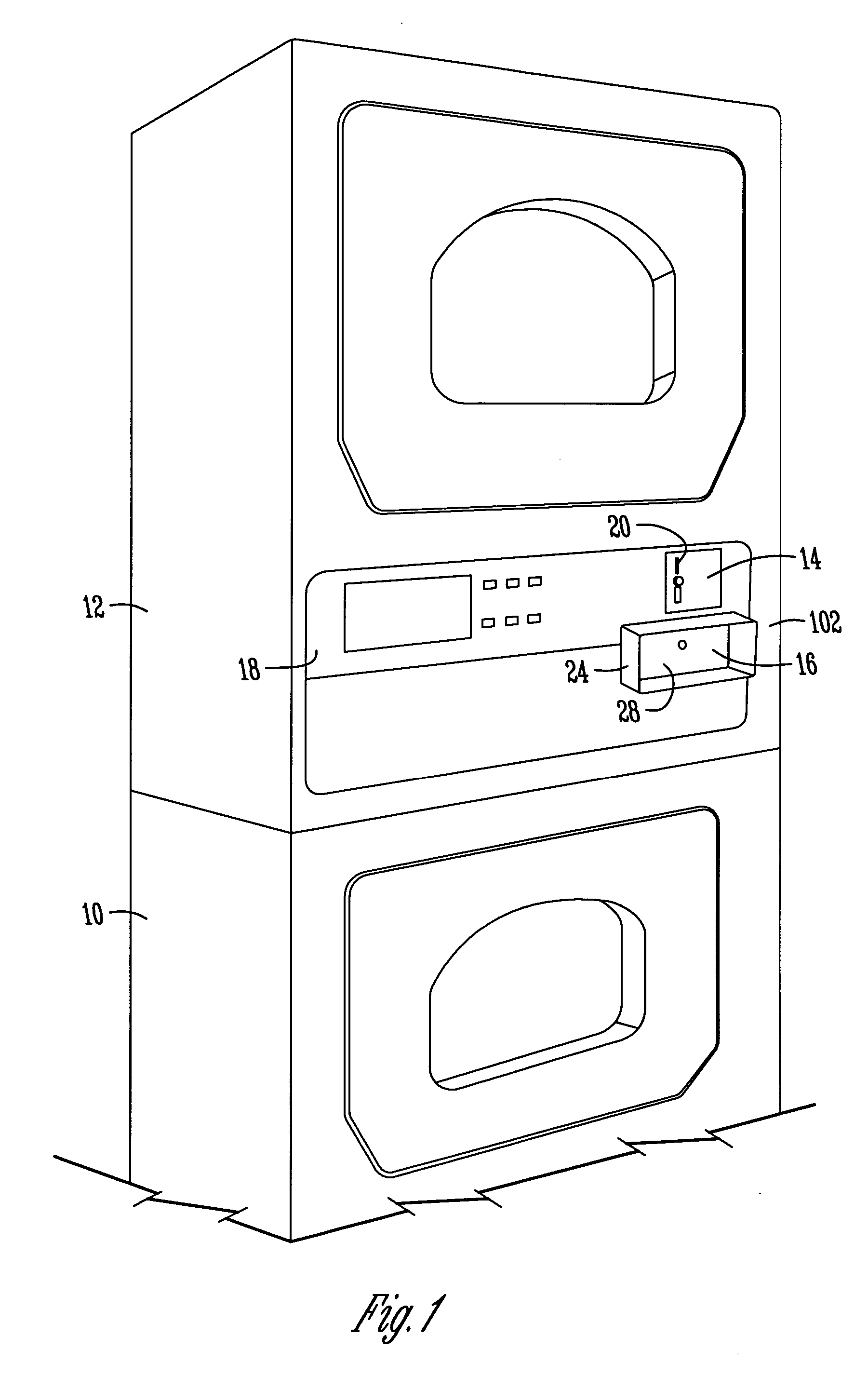
[0026]FIG. 1 shows a commercial laundry appliance with a washer 10 and dryer 12 arranged in a stacked unit. The washer 10 and dryer 12 are coin operated, and include a coin deposit 14, and the improved coin box assembly 16 of the present invention. A control panel 18 provides user control of the washer 10 and dryer 12 when coins, normally quarters, are deposited in the coin slot 20.

[0027] It is understood that the coin box assembly 16 can be used on stand alone washers and dryers, stacked washers and dryers, as well as other coin operated machines, such as vending machines.

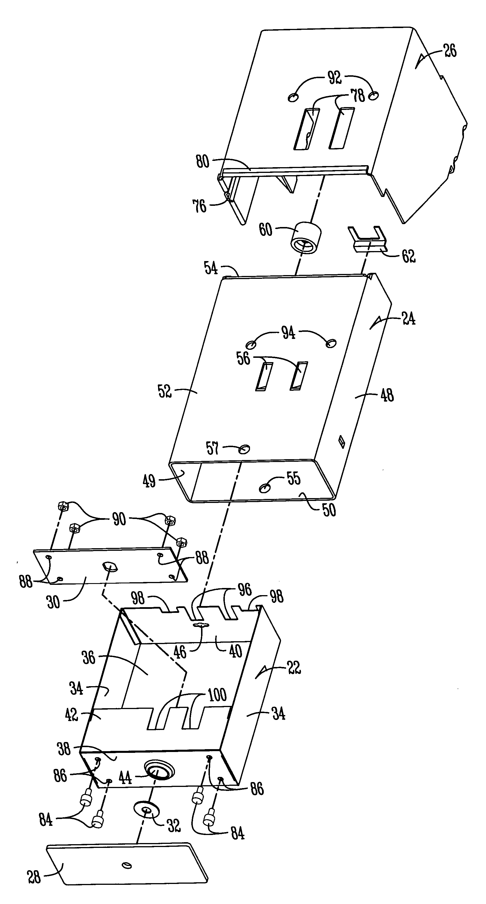
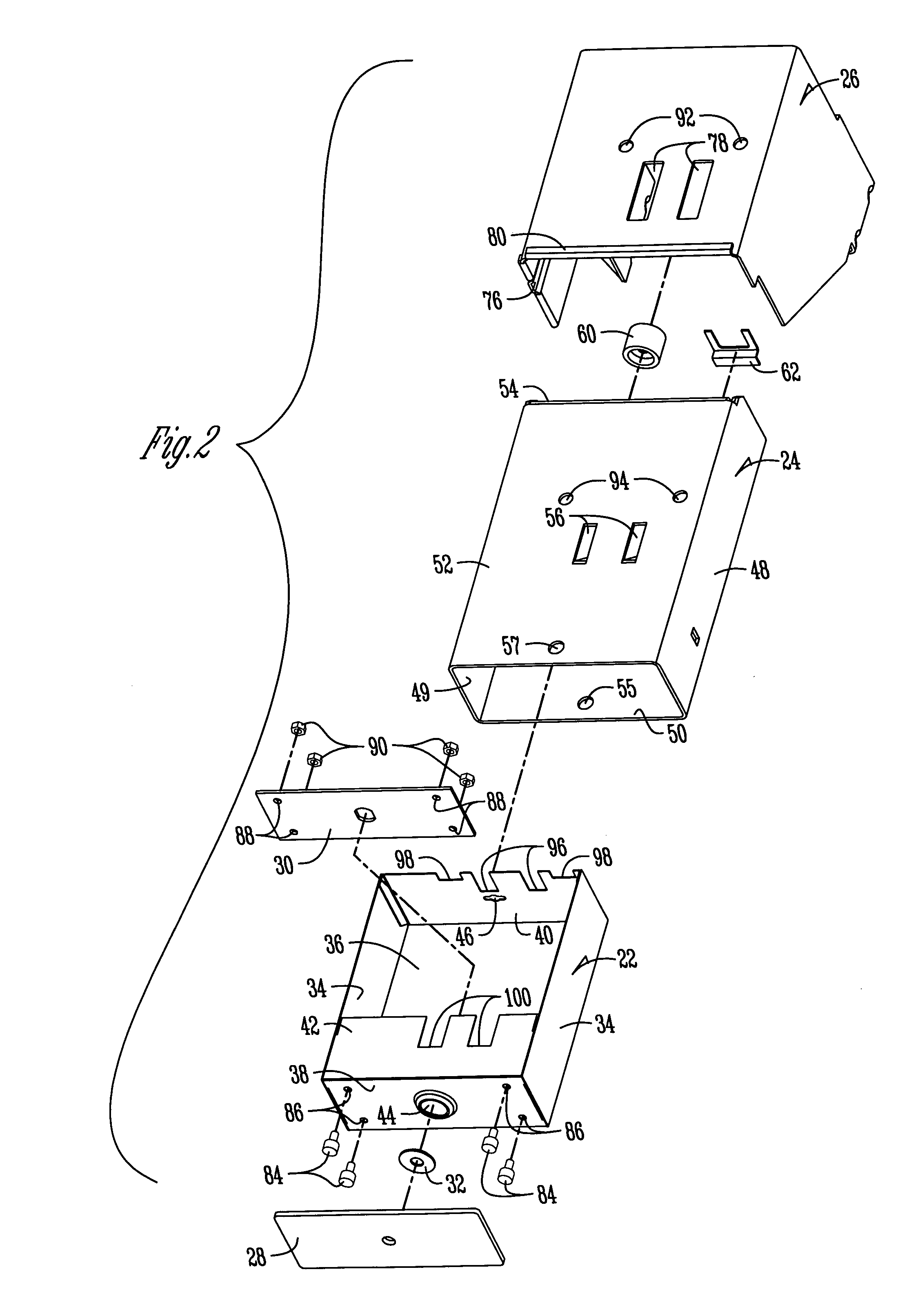
[0028] The components of the coin box assembly 16 are best shown in FIG. 2. The primary components are a coin box 22, a vault 24, and a mounting bracket 26. The assembly further includes an external security plate 28, an internal lock plate 30, and a free-spinning washer 32.

[0029] The coin box 22 includes opposite side walls 34, a bottom wall 36, a front wall 38, a rear wall 40, and a partial top wall 42. The f...


PUM


Abstract

An improved coin box assembly is provided for a coin operated laundry appliance. The assembly includes a mounting bracket mounted in the cabinet of the appliance, a vault mounted within the mounting bracket, and a coin box mounted within the vault. The mounting bracket and vault provide double-wall protection for the coin box so as to inhibit prying. The assembly further includes external and internal plates sandwiching the front wall of the coin box to prevent cutting of the front wall of the coin box. A freely-spinning washer is mounted between the front plate and the front wall of the coin box to preclude a hole saw from cutting out the lock cylinder of the coin box.

Description

BACKGROUND OF THE INVENTION [0001] Commercial laundry appliances used in commercial laundry facilities, university and college student housing, and other public settings, are typically coin operated, and accordingly, include a coin box for storing the coins deposited by users to operate the washer and dryer machines. It is not unusual for the coin boxes to hold several hundred dollars of quarters, which, unfortunately, creates theft problems. For example, it has been known for thieves to use drilling, prying, torching, and cutting tools to gain access to the coin box so as to steal the money therein. [0002] Prior art coin operated appliances have been designed with coin boxes mounted in a small protective vault so as to make theft more complicated. However, theft remains a problem, particularly as battery operated tools make it easier for a thief to breach weak points in the security of the coin box and / or vault. [0003] For example, existing designs for the coin box of commercial ap...

Claims


Application Information

Patent Timeline
Patent Type & Authority Applications(United States)
IPC IPC(8): G07B15/00
CPCG07F9/06Y10T70/5128
Inventor SELOVER, MICHAEL D.
Owner MAYTAG
Learn More