
An enhanced heat transfer tube with discrete bidirectionally inclined ribs

a heat transfer tube and bidirectional inclined technology, applied in tubular elements, corrosion prevention, coatings, etc., can solve the problems of high cost of tube manufacturing, low efficiency, bulky and material-cost of ordinary shell and tube heat exchangers using circular tubes, etc., to achieve enhanced heat transfer, low additional pressure loss, and simple manufacturing process

Inactive Publication Date: 2007-01-04
TSINGHUA UNIV
View PDF11 Cites 6 Cited by
  • Summary
  • Abstract
  • Description
  • Claims
  • Application Information

AI Technical Summary

Benefits of technology

[0010] Compared with the existing techniques, the present invention has the virtues of significant enhanced heat transfer, low additional pressure loss and simple manufacturing process. In the turbulent flow region, the heat transfer coefficient of the DBIR-tube is 80% to 150% higher than that of the smooth tube, and 30% higher than that of the transverse grooved tube (one best enhanced tube), while the pressure loss is 20% to 50% lower than that of the transverse grooved tube. With regard to the convection heat transfer happened in transition regions, the heat transfer effect is also greatly improved. Compared with the transverse grooved tube, the DBIR-tube is of good anti-fouling performance because there is no back flow (transverse vortex flow) formed near the bidirectionally inclined ribs and there is no stagnant area formed inside the tube.

Problems solved by technology

However, ordinary shell and tube heat exchangers using circular tubes are bulky and material-cost, due to their weak heat transfer.
Most of the existing enhanced tubes suffer from high flowing resistance or pressure drop, fouling (dust accumulating) in the back-flow areas near the grooves or ribs, as well as low efficiency and high cost in tube manufacturing.

Method used


Image

  • An enhanced heat transfer tube with discrete bidirectionally inclined ribs
  • An enhanced heat transfer tube with discrete bidirectionally inclined ribs
  • An enhanced heat transfer tube with discrete bidirectionally inclined ribs

Examples


first embodiment

The First Embodiment

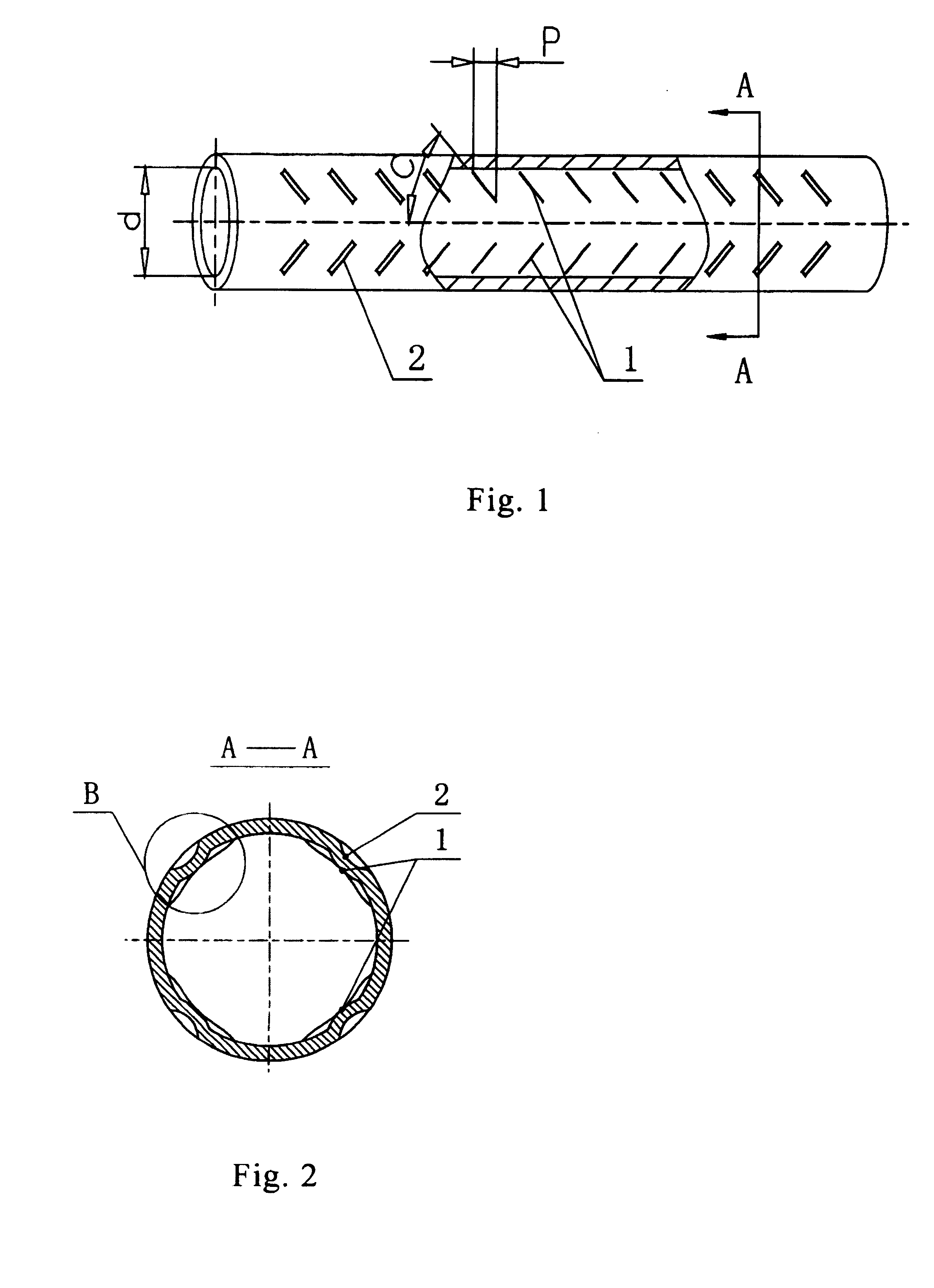
[0017]FIG. 1 shows the structure of a DBIR-tube of the present invention. The inner surface of the tube is provided with a plurality of discrete, two-direction helical protrusions (named as internal discrete double helical ribs or internal discrete bidirectionally inclined ribs). The outer surface of the tube is provided with a plurality of discrete double helical grooves.

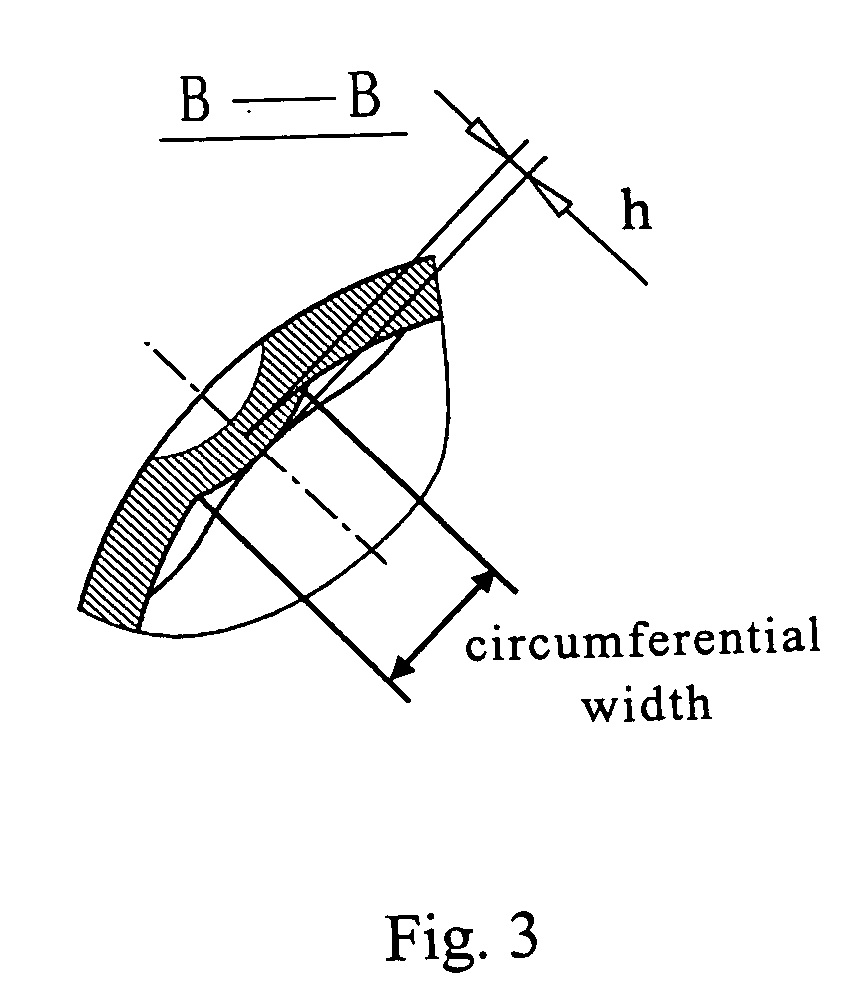
[0018] In FIGS. 1 and 2, reference numeral 1 designates the discrete double helical ribs, and reference numeral 2 designates the discrete double helical grooves, with the helical ribs and the corresponding helical grooves being formed simultaneously during processing. In FIG. 1, reference sign “d” designates the hydrodynamic inner diameter of the tube, reference sign “P” designates the axial length of each internal inclined rib, and reference sign “C” designates the helical angle of the internal inclined ribs. In FIG. 3, reference sign “h” designates the height of the internal inclined ribs. Th...

second embodiment

The Second Embodiment

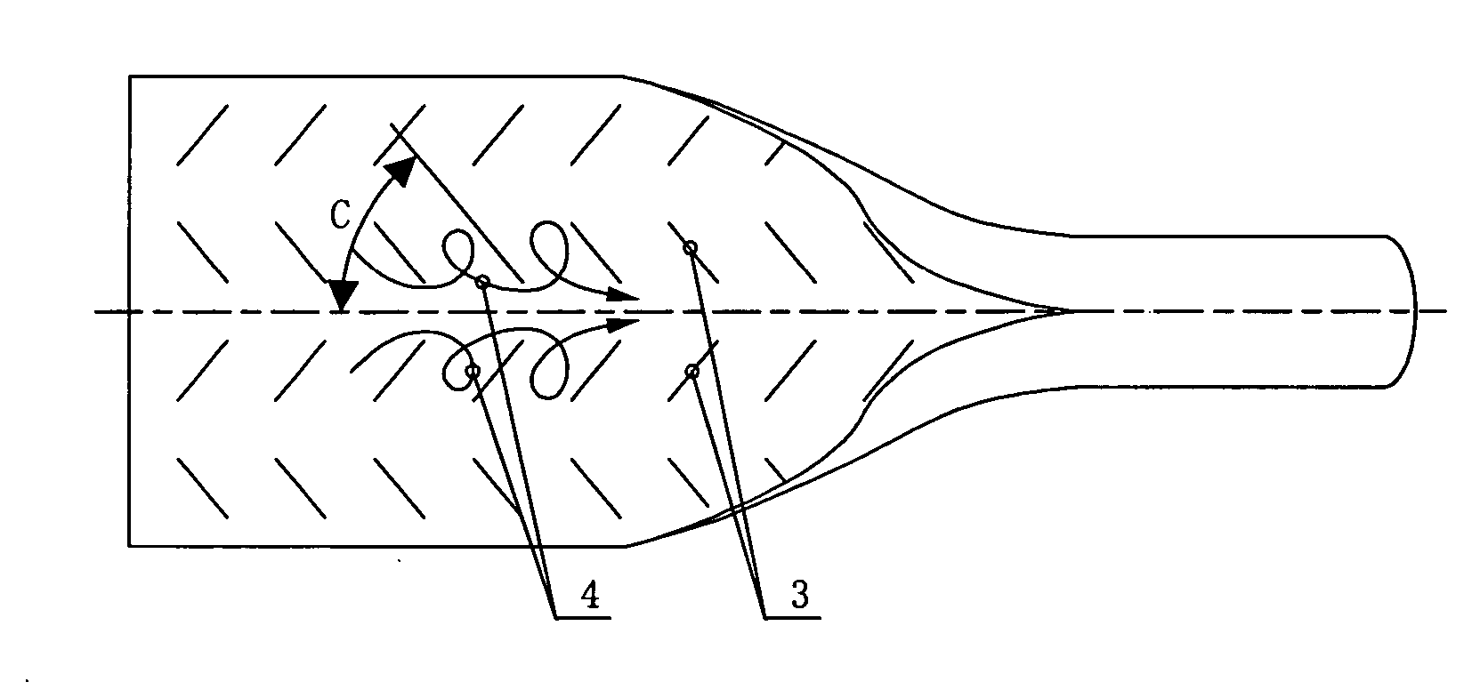
[0019]FIG. 4 shows the structure of another DBIR-tube of the present invention in a circumferentially part-deployed schematic view. The inner surface of the tube is provided with a plurality of discrete, two-direction helical protrusions (discrete bidirectionally inclined ribs or discrete double inclined ribs). The outer surface of the tube is smooth, without any protrusion or groove.

[0020] In FIG. 4, reference numeral 3 designates the discrete bidirectionally inclined ribs, which are symmetrical disposed. Each pair of inclined ribs, composed of an inclined rib which is orientated in a right hand declining direction and a circumferentially neighboured inclined rib which is orientated in a left hand declining direction, form a vortex generator. In each cross-section of the tube, there are two vortex generators formed by four inclined ribs. In FIG. 4, reference sign “C” designates the helical angle of the internal inclined ribs, and C≈±50°, wherein the positive s...

third embodiment

The Third Embodiment

[0021]FIG. 5 shows the structure of yet another DBIR-tube of the present invention in a circumferentially part-deployed schematic view. The inner surface of the tube is provided with a plurality of discrete, two-direction helical protrusions (bidirectionally inclined ribs). The outer surface of the tube is provided with a plurality of discrete double helical grooves.

[0022] In FIG. 5, reference numeral 5 designates the discrete double helical ribs which are asymmetrically arranged, and reference numeral 6 designates the discrete double helical grooves which are also asymmetrically arranged. On the inner surface, each pair of inclined ribs, composed of an inclined rib which is orientated in a right hand declining direction and a circumferentially neighboured inclined rib which is orientated in a left hand declining direction, form a vortex generator. Within a small circumferential segment of the tube, which has an axial length of less than 0.5 d, there are three v...


PUM

PropertyMeasurementUnit
Timeaaaaaaaaaa
Timeaaaaaaaaaa
Timeaaaaaaaaaa

Abstract

An enhanced heat transfer tube with discrete bidirectionally inclined ribs (DBIR-tube) provides enhanced convective heat transfer both in laminar and turbulent flow regions. The inner surface of the tube is formed with bidirectionally inclined ribs, including left hand inclined ribs and right hand inclined ribs, with the ribs being in the form of discrete strip-like protrusions which respectively form a certain angle with respect to the axis of the tube and incline in two directions. With the hydrodynamic inner diameter of the tube represented by “d”, each bidirectionally inclined rib has a height less than or equal to 0.2 d, a circumferential width less than or equal to 0.5 d, and an axial length less than or equal to 2 d. A certain angle formed between the axis of each rib and the axis of the tube is ±5° to ±85°, the positive sign meaning that the internal rib is orientated in a right hand declining direction, and the negative sign meaning that the internal rib is orientated in a left hand declining direction.

Description

TECHNICAL FIELD [0001] The invention relates to an enhanced heat transfer tube with discrete bidirectionally inclined ribs, which belongs to the field of enhanced heat transfer and heat exchanger. BACKGROUND ART [0002] Shell-and-tube type heat exchangers have extensively and greatly application in areas such as petroleum engineering, chemical engineering, and power engineering. Smooth circular tubes, which have the advantages of easy manufacturing, high reliability and low cost, are generally used in shell-and-tube type heat exchangers. However, ordinary shell and tube heat exchangers using circular tubes are bulky and material-cost, due to their weak heat transfer. In order to overcome these shortages, a variety of enhanced heat transfer tubes have been adopted for substituting smooth circular tubes. Various enhanced convective heat transfer tubes have been invented in recent 30 years based on wall surface disturbing enhancement techniques. Especially, rough surface enhanced tubes,...

Claims


Application Information

Patent Timeline
IPC IPC(8): F28F13/18F28F1/42
CPCF28F1/426F28F1/42
Inventor GUO, ZENGYUANMENG, JI-ANHU, WEILINLI, ZHIXIN
Owner TSINGHUA UNIV
Learn More