Crankcase with bottom plate
a crankcase and bottom plate technology, applied in the direction of auxillary lubrication, pressure lubrication with lubrication pump, oil pump, etc., to achieve the effect of preventing the release of lubricant to the ambient, reducing the number of seal structures of the crankcase, and ensuring the operation of safety
- Summary
- Abstract
- Description
- Claims
- Application Information
AI Technical Summary
Benefits of technology
Problems solved by technology
Method used
Image
Examples
Embodiment Construction
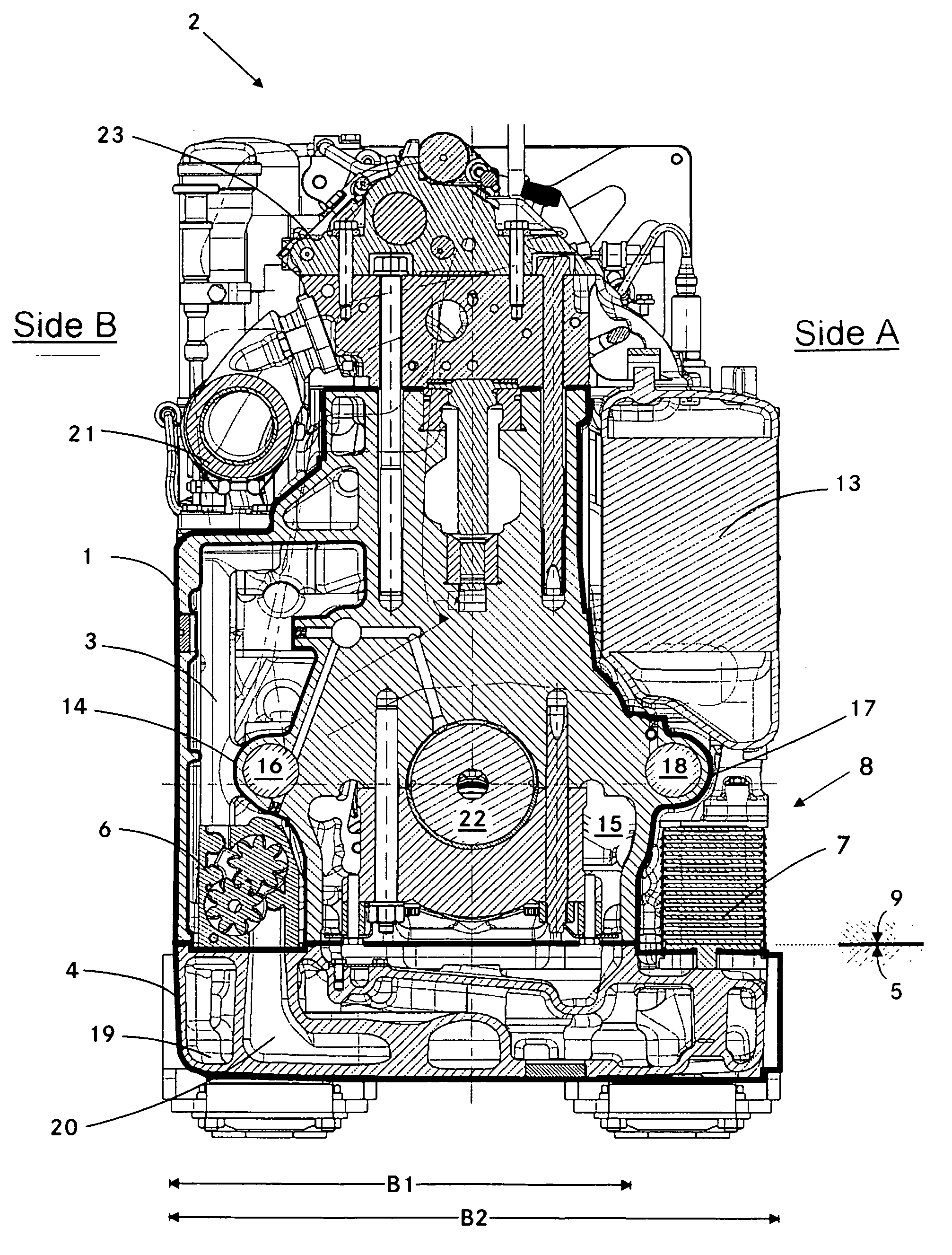
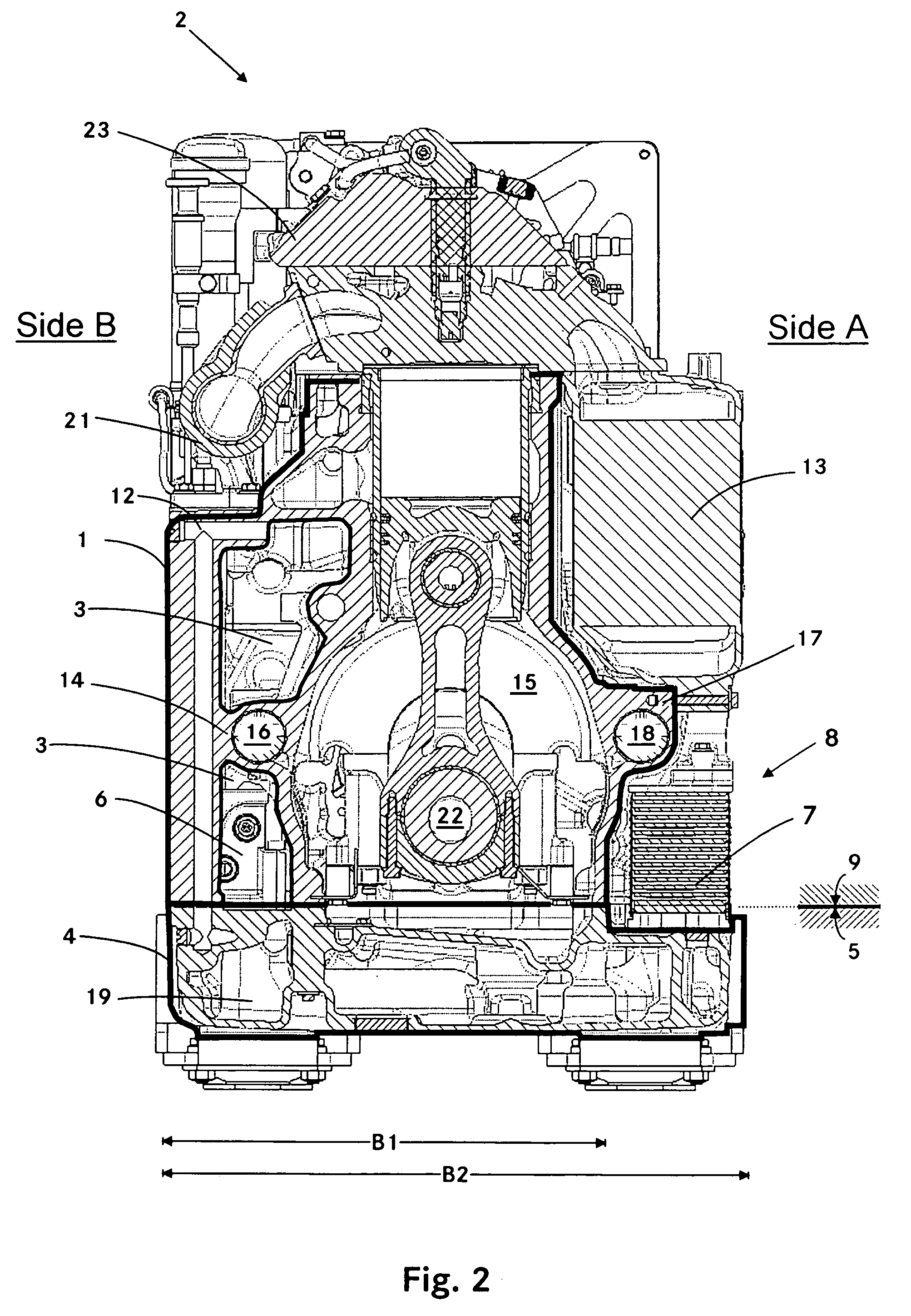
[0012]FIG. 1 shows a first cross-sectional view of an internal combustion engine 2 with in-line arrangement of the cylinders which are vertically oriented. The engine 2 includes a crankcase 1 which is closed toward the ambient by a bottom plate 4. The bottom plate 4 has a top side 9 which abuts the underside 5 of the crankcase. Within the crankcase 1, there is a chamber 3 for collecting lubricant. As shown in FIG. 1, the chamber 3 is disposed on a B-side of the internal combustion engine 2. At the bottom side 5 of the crankcase, the chamber 3 is open.
[0013] The bottom plate 4 includes the channels for conducting fluids, suction locations for the pumps 6 and lubricant storage chambers. The reference numeral 29 for example designates such a lubricant storage space and the reference numeral 20 designates a suction channel which extends from a suction location (not shown) to the pumps 6. By way of the bottom plate 4, a dry sump lubrication system is provided.
[0014] In accordance with ...
PUM
 Abstract
Description
Claims
Application Information
 - Generate Ideas
- Intellectual Property
- Life Sciences
- Materials
- Tech Scout
- Unparalleled Data Quality
- Higher Quality Content
- 60% Fewer Hallucinations
Browse by: Latest US Patents, China's latest patents, Technical Efficacy Thesaurus, Application Domain, Technology Topic, Popular Technical Reports.
© 2025 PatSnap. All rights reserved.Legal|Privacy policy|Modern Slavery Act Transparency Statement|Sitemap|About US| Contact US: help@patsnap.com


