Method for digital die cutter for containerboard packaging

a technology of containerboard packaging and die cutter, which is applied in the direction of metal working apparatus, etc., can solve the problems of limiting the production capacity of a line, all of the blades needing periodic replacement, and the tooling cost of creating a typical cutting die is relatively high, so as to eliminate the need for die storage and management and reduce downtime

Inactive Publication Date: 2007-01-04
INT PAPER CO
View PDF16 Cites 10 Cited by
  • Summary
  • Abstract
  • Description
  • Claims
  • Application Information

AI Technical Summary

Benefits of technology

[0006] The present invention therefore provides a solution to the labor-intensive prior methods for producing dies for cutting, indenting and scoring cardboard boxes and eliminates need for die storage and management and reduces downtime during grade changes. In accordance with the present invention, a digital die cutting system is provided comprising at least a first addressable die cutter having a surface. The die cutter has a plurality of knives arranged in an array on the surface. Each of the knives are extendable above and retractable below the surface. The system also has a controller for individually addressing, extending, setting, and retracting each of the knives above and below the surface. A central processing unit receives an image of a pattern to be cut by selected ones of the knives and processes the image into signals for the controller to extend selected ones of the knives to correspond to the shape of the pattern. Finally, a means is provided for presenting the surface of the die cutter to one surface of the panel to be die cut when at least one of the knives is extended.

Problems solved by technology

The tooling costs of creating a typical cutting die are relatively high, and can serve as a barrier to new product design and introduction.
While the cutting die can be reused, some or all of the blades periodically need to be replaced because of wear and / or damage.
Setting up the printing plates as well as maintenance and repair are all time-consuming processes that require significant machine shutdown time, thereby limiting the production capability of a line.
Finally, the large amount of manufacturing floor space needed to house the die inventory, die management, and care from damage all add to the cost of the workflow.

Method used


Image

  • Method for digital die cutter for containerboard packaging
  • Method for digital die cutter for containerboard packaging
  • Method for digital die cutter for containerboard packaging

Examples


Embodiment Construction

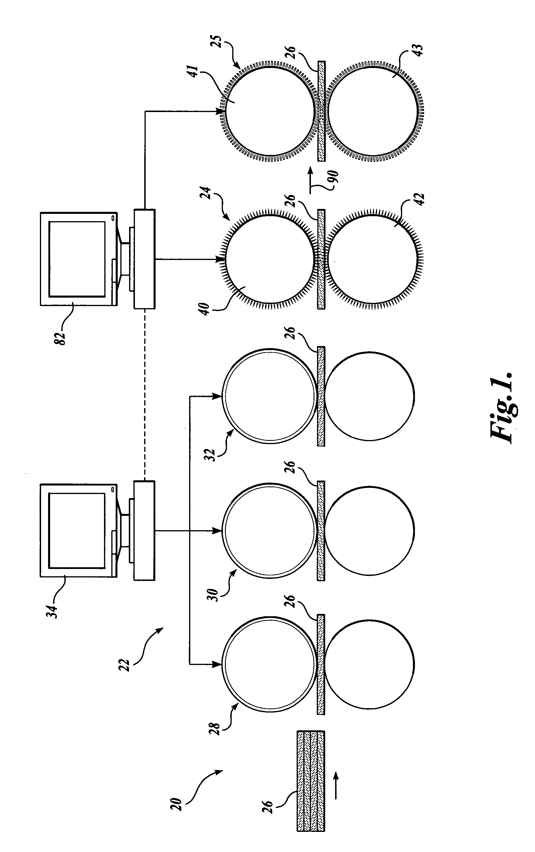
[0021] Referring to FIG. 1, a schematic diagram of a box-making machine includes a feed station 20, a printing station 22, a die cutting station 24, and an indenting station 25. A stack of previously cut corrugated boards 26 are shown accumulated at the feeding station. Individual boards 26 are sequentially fed through the printing station 22, the die cutting station 24, and the indenting station 25. In this illustration, the printing station comprises a three-color press including red printing rolls 28, green rolls 30, and blue rolls 32. Red, blue, and green inks, for example, are applied to these three stations to produce a three-color image on the final board issuing from the printing station 22. The printing station 22 is controlled from a processing unit 34 that controls the ink flows, rotation, and registration of the printing press in a conventional manner. Color separations for each ink appear in each printing plate and are used to reproduce the composite image.

[0022] The b...


PUM

PropertyMeasurementUnit
diameteraaaaaaaaaa
axis of rotationaaaaaaaaaa
rotationaaaaaaaaaa

Abstract

A digital die cutting system including at least a first addressable die cutter having a surface carrying a plurality of knives in an array, each of the knives extendable and retractable above and below the surface is presented/provided. A controller is provided for individually addressing, and extending, and retracting the knives above and below the surface. A central processing unit receives an image of a pattern to be cut by selected ones of the knives, processes that image for a controller, which then extends selected ones of the knives to correspond to the shape of the pattern. The die cutter is then presented by conventional apparatus to the surface of a panel to be die cut when at least some of the knives are extended.

Description

FIELD OF THE INVENTION [0001] The present invention relates to die cutters, and more particularly, to an apparatus for replacing conventional dies for cutting and scoring paper products such as corrugated board used in containerboard packaging. BACKGROUND OF THE INVENTION [0002] Corrugated cardboard comprises an inner or bottom ply and outer or top ply between which is sandwiched a third ply that is fluted. These plies are adhesively secured to each other to form a finished corrugated board. Normally, the corrugator machine produces a continuous sheet of cardboard, which is cut to produce individual sheets of board of a given size. These cardboard sheets are stacked, transported, and later fed into a box-making machine that performs two key manufacturing steps, printing and die cutting. [0003] Typical box-making machines include, for example, a one to four color flexographic print station. Each of the stations houses a flexible printing plate and associated hardware for metering and...

Claims


Application Information

Patent Timeline
Patent Type & Authority Applications(United States)
IPC IPC(8): B26D5/20
CPCB26D1/42B26F1/24B26D5/02Y10T83/162
Inventor HIRAHARA, EDWINLEE, DAVID L.
Owner INT PAPER CO
Why Eureka
Try Eureka