Eureka AIR delivers breakthrough ideas for toughest innovation challenges, trusted by R&D personnel around the world.

Bone implant device and methods of using same

a bone implant and implant technology, applied in the field of bone implant devices, can solve the problems of device which is unable to perform the intended function, inability to achieve the intended function, and inability to suppress the very bone formation needed, so as to prevent suppression or reduction of bone growth, minimize contact, and minimize the effect of conta

Inactive Publication Date: 2006-12-28
UNIGENE LABORATORIES +1
View PDF31 Cites 15 Cited by
  • Summary
  • Abstract
  • Description
  • Claims
  • Application Information

AI Technical Summary

Benefits of technology

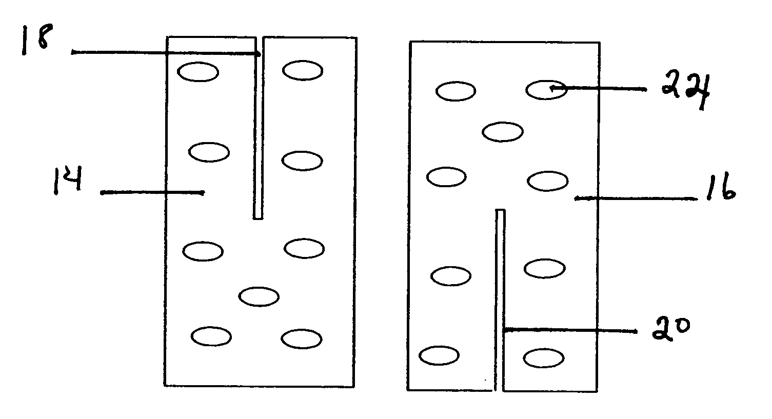
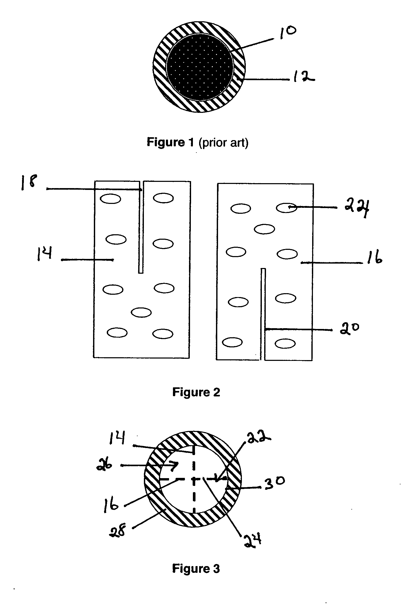
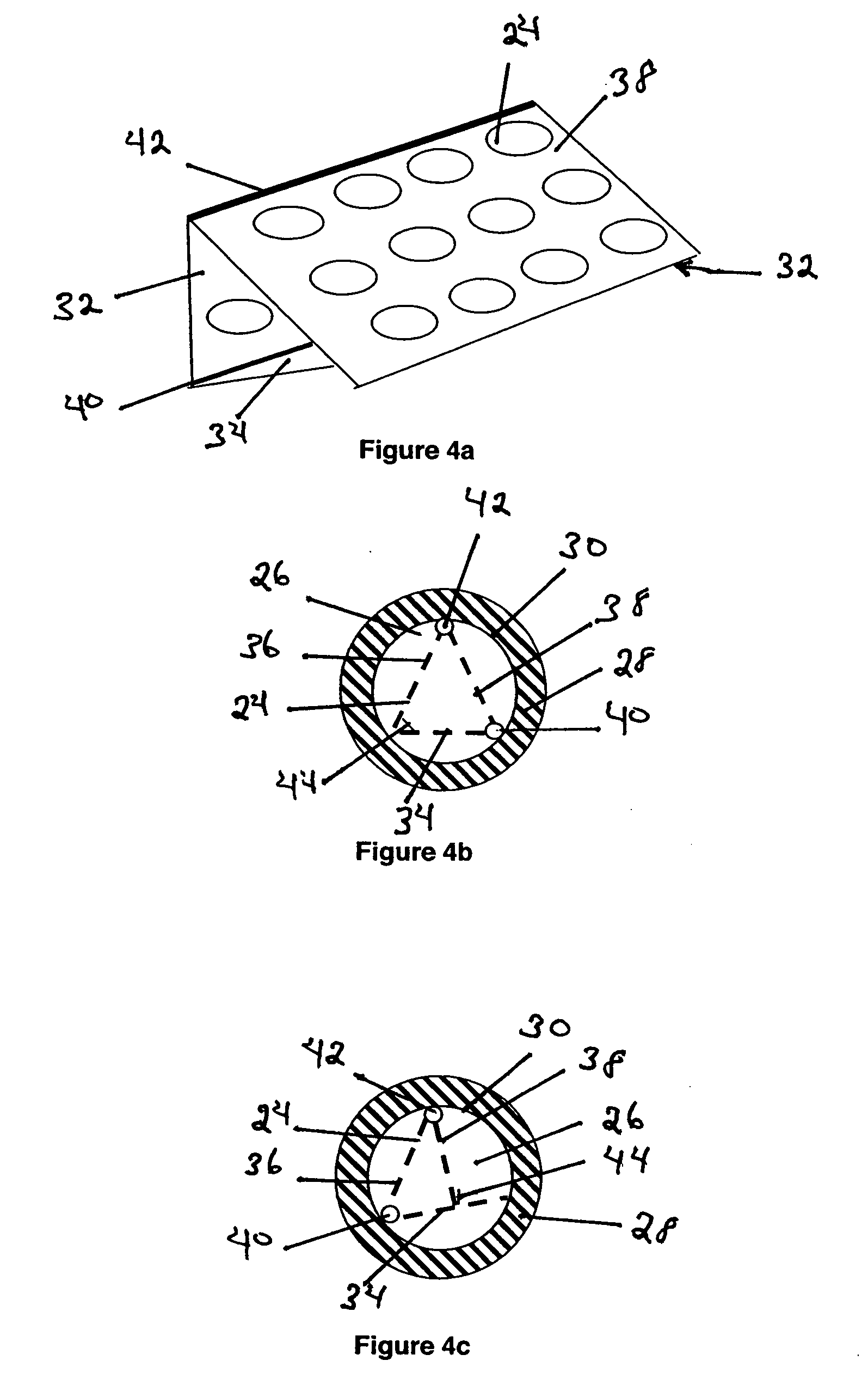
[0015] The invention is additionally directed, in another embodiment, to a method for repairing a bone fracture in a subject in need of such repair. The method comprises sufficiently stabilizing a fractured portion of a bone of the subject for a time sufficient to permit bone growth to repair the fracture, wherein the fractured portion is stabilized by inserting into a region adjacent the fractured portion a bone implant device according to the invention. The device, which is described further herein, comprises at least two interconnected plate members, wherein at least one plate member defines a plurality of apertures adapted to permit bone growth through the aperture from an interior portion of the fractured bone. This arrangement aids in securing the device within the bone. The device is configured and adapted to minimize contact with the interior surface of the bone, such that no more than 75% of the bone's inner surface is in contact with the bone's inner surface following its installation, to thus aid in preventing suppression or reduction of bone growth by osteoblasts located within the marrow cavity and / or along the inner bone surface.
[0017] In a still further embodiment the invention is directed to a method for anchoring a prosthetic appendage to the body of a subject. The method comprises inserting a first end portion of a bone implant device within a bone stub remaining at a location where the prosthesis is to be anchored. The bone implant device comprises a plurality of interconnected plate members. At least one plate member defines a plurality of apertures adapted to permit bone growth through the aperture from an interior portion of the bone stub in which the device is implanted. The device is configured and adapted to minimize contact with the interior portion of the bone stub, such that no more than 75% of the bone's inner surface is in contact with the device following its installation, to assist in preventing suppression or reduction of bone growth by osteoblasts located within the marrow cavity of the stub and / or along the periphery of the inner bone surface. The prosthesis is secured to a second, opposed end portion of the bone implant device.

Problems solved by technology

One major difficulty associated with the installation of such bone implants, however, is to ensure their attachment to the adjacent skeletal bone.
Moreover, the insertion technique often tends to damage or destroy osteoblasts located around the inner surface of the medullary canal, thus preventing or at least suppressing the very bone formation needed for securing the implant within the bone.
The use of screws and / or pins as the sole means for retaining such devices in position may lead to additional complications.
Failure of a single screw or pin, e.g., while the limb containing the bone is in use following the surgery, requires a further surgical procedure to repair or entirely replace the insert since the lack of any other fixation means results in a device which is unable, under such circumstances, of performing its intended function.
This is, of course, highly undesirable.
The use of bone cements creates additional difficulties.
While such cements do tend to provide the initial fixation necessary to permit healing following surgery, their use typically results in a very stiff overall structure, which is often prone to loosening over time.
Furthermore, their presence may provoke tissue reactions in individuals sensitive to the composition of these materials.
Each of the above-described methodologies requires lengthy and relatively difficult procedures in the midst of the implant operation, dealing with the introduction and packaging of foreign bone matter into the patient's bone structure.
Not all of these concerns have yet been resolved.

Method used


Image

  • Bone implant device and methods of using same
  • Bone implant device and methods of using same
  • Bone implant device and methods of using same

Examples


Embodiment Construction

[0035] In one embodiment the invention is directed to a bone implant device comprising two or more interconnected plate members. At least one plate member defines a plurality of apertures adapted to permit bone growth through the aperture from an interior portion of a bone in which the device is implanted. The number and arrangement of these apertures is an important consideration in fabricating the plate members of the invention and the appropriate choices involving these parameters can be readily made by those having ordinary skill in this art. Bone growth through the apertures aids in securing the device within the bone marrow cavity. The device is configured and adapted to minimize contact with the interior portion of the bone to aid in preventing suppression or reduction of bone growth by osteoblasts located within the marrow cavity and / or along the inner bone surface. As used herein, the phrase minimize (or minimal) contact is defined to mean that no more than 75% of the bone'...


PUM


Abstract

A bone implant device comprising a plurality of interconnected plate members, at least one plate member defining a plurality of apertures therein adapted for permitting bone growth there through from an interior portion of the bone in which the device is implanted for aiding in securing the device within the interior portion, and wherein the device is configured and adapted to minimize contact with an interior surface of the bone. The device is useful in applications including, but not limited to, repairing bone fractures, modeling bone in growing subjects, service as artificial joints and anchoring prostheses, such as an artificial limb, to a bone stub in the body of a subject.

Description

CROSS-REFERENCE TO RELATED APPLICATION [0001] This application claims the benefit of the priority of Provisional Application No. 60 / 682,456 filed May 19, 2005, the contents of which are specifically incorporated by reference herein.BACKGROUND OF THE INVENTION [0002] 1. Field of the Invention [0003] The invention relates to a bone implant device as well as to methods for its use. More particularly, the invention is directed to such a device having minimal contact with an inner surface of a bone marrow cavity wherein it is installed, while yet securely supporting, for example, another bone portion or fragment, or a prosthetic device or limb, to which the device is also connected. [0004] 2. Description of the Prior Art [0005] Bone implants are frequently inserted into the skeletal structure of humans, particularly for, but not limited to, uses such as repairing bone fracture(s) and other bone trauma, for joint (e.g., hip, shoulder, knee, ankle, etc.) replacement, and for attaching pros...

Claims


Application Information

Patent Timeline
Patent Type & Authority Applications(United States)
IPC IPC(8): A61F2/30
CPCA61B17/72A61B17/742A61B17/7283A61B17/7258
Inventor VIGNERY, AGNESMEHTA, NOZER M.GILLIGAN, JAMES P.
Owner UNIGENE LABORATORIES
Why Eureka
Eureka Blog
Learn More