Garbage pressing device for environment-friendly recycling
A garbage and environmental protection technology, which is applied in the field of pressing devices, can solve the problems of ineffective disinfection of garbage, inability to briquette, etc., and achieves the effect of high work efficiency and convenient briquetting work.
- Summary
- Abstract
- Description
- Claims
- Application Information
AI Technical Summary
Problems solved by technology
Method used
Image
Examples
Embodiment 1
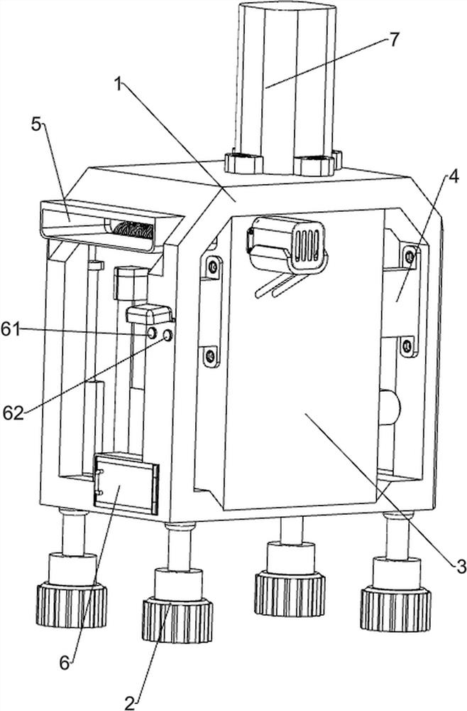
[0040] A garbage pressing device for environmental protection recycling, such as Figure 1-Figure 7 As shown, it includes a supporting chassis 1, a fixed bottom column 2, a compression box body 3, a fixed connecting plate 4, a feeding square tube 5, a start button 61, a stop button 62, a garbage pressing mechanism 7 and a discharge mechanism 8. Four fixed base columns 2 are fixedly connected to the bottom of the bottom frame 1 at intervals, fixed connecting plates 4 are fixedly connected to the rear upper part of the inner walls on the left and right sides of the supporting frame 1, and a compression box is fixedly connected between the fixed connecting plates 4 on the left and right sides body 3, the upper right side of the compression box body 3 is connected with a feeding square pipe 5, the upper right side of the support base frame 1 is provided with a start button 61, and the upper right side of the support base frame 1 is provided with a stop button 62, and the stop butto...
Embodiment 2
[0045] On the basis of Example 1, such as Figure 7-Figure 14 As shown, a compression mechanism 9 is also included, and the compression mechanism 9 includes a connecting plate 91, a positioning slide bar 92, a storage straight plate 93, a limit spring 94, a protective shell 95, a driving rack 96, a positioning vertical rod 97, a first positioning Minor shaft 98, driven gear 99, positioning belt 910, second positioning minor shaft 911, positioning bottom block 912 and fixed block 913, positioning slide bar 92 fixedly fixed on the left and right sides of the slotted pressing plate 75, and positioning slide bar on the left and right sides Between 92, a connecting plate 91 is slidably provided, and the lower part of the compression box 3 is slidably provided with a storage straight plate 93. The storage straight plate 93 is set on the connecting plate 91, and the receiving straight plate 93 is slidably connected with the connecting plate 91, and the bottom of the connecting plate 9...
Embodiment 3
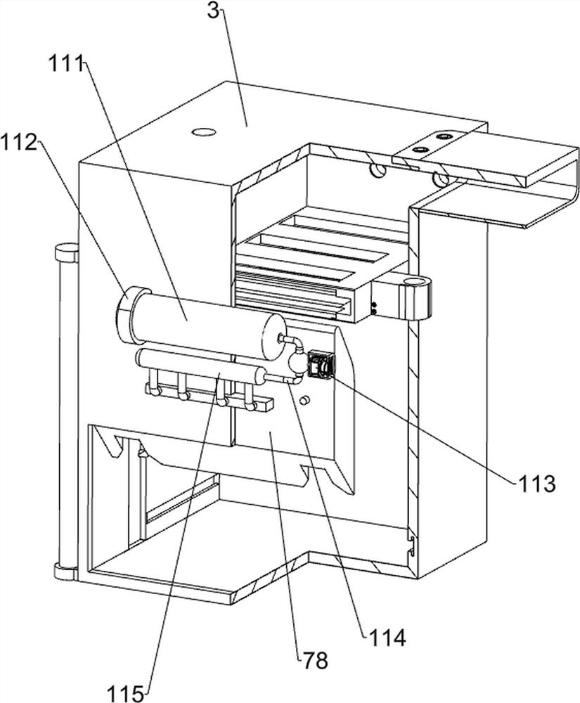
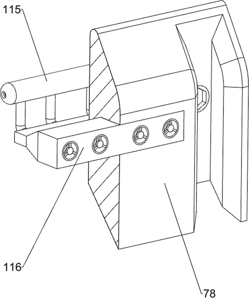
[0050]On the basis of embodiment 1 and embodiment 2, such as Figure 7 and Figure 15-Figure 17 As shown, a sterilizing mechanism 11 is also included, and the sterilizing mechanism 11 includes a fuel cylinder 111, a fixed frame 112, a spherical solenoid valve 113, an air guide pipe 114, a shunt conduit 115 and a heating spout 116, and the upper part of the outer front side of the compression box 3 is symmetrical A fixed frame 112 is fixedly connected, and a fuel cylinder 111 is connected between the fixed frames 112 on the left and right sides. A heating spout 116 is embedded in the lower side of the front part of the compression box body 3, and a shunt conduit 115 is connected to the heating spout 116. An air guide pipe 114 is connected between the fuel cylinders 111 , and a spherical solenoid valve 113 is connected to the air guide pipe 114 .
[0051] Also includes a sealing mechanism 12, the sealing mechanism 12 includes a slotted sealing plate 121, a limit roller 122, a s...
PUM
 Abstract
Description
Claims
Application Information
 - Generate Ideas
- Intellectual Property
- Life Sciences
- Materials
- Tech Scout
- Unparalleled Data Quality
- Higher Quality Content
- 60% Fewer Hallucinations
Browse by: Latest US Patents, China's latest patents, Technical Efficacy Thesaurus, Application Domain, Technology Topic, Popular Technical Reports.
© 2025 PatSnap. All rights reserved.Legal|Privacy policy|Modern Slavery Act Transparency Statement|Sitemap|About US| Contact US: help@patsnap.com


