Wind powered turbine engine

a wind turbine and engine technology, applied in the direction of wind turbines, machines/engines, mechanical equipment, etc., can solve the problems of no longer profitable systems, achieve the effects of increasing the velocity of redirected wind energy, maximizing the cross section of energy, and increasing the available energy

Inactive Publication Date: 2006-12-28
ENVISION
View PDF38 Cites 11 Cited by
  • Summary
  • Abstract
  • Description
  • Claims
  • Application Information

AI Technical Summary

Benefits of technology

[0004] Secondly, to produce a wind power unit to more efficiently harness useable levels of energy from a broader range of wind speeds.
[0007] Existing propeller turbine wind power units of present state of the art are not harnessing a very high percentage of energy from the cross section of wind addressed by such units. Three bladed propellers do not harness much of that energy. Present state of the art arrangements with larger numbers of blades might present some improvement within the scope of smaller sized systems. The inner 50% of the radius of propeller driven wind power systems is not harnessing much of the cross section of energy being addressed. The most practical solution to dealing with the inner 50% of the radius of propeller blades from their axle center, is to efficiently block off that area, and access the redirected energy with turbine blades extending radially beyond the blocked off area.
[0008] This invention, in its presently preferred embodiment, employs a spherical head arrangement, hereinafter referred to as a “speedball” in front of, and covering more than 50% of the radius from axle center to the outer tips of its turbine blades. The speedball increases the velocity of redirected wind energy, to more completely address a larger number of shorter turbine blades.
[0010] Present state of the art wind turbine systems tend to be limited as to the range of wind speeds from which they can harness a useful amount of wind energy. The spherical head arrangement increases the speed of the wind redirected from that inner 50% of the center to blade tip radius of the turbine rotor and blade assembly, but the faster moving wind is inclined to address only the inner radial portion of the turbine blades. To even out wind flow through the operating aperture containing the multi-bladed turbine rotor, a compound curved intake scoop arrangement is used to scoop inward a larger volume of incoming wind, toward the said shorter and more numerous turbine blades. This annular ring scoop is further designed with an inner facing airfoil arrangement, which increases the velocity of the captured wind, to much the same extent as that achieved by means of the said spherical head. The overall objective is to increase incoming wind speed, and then have this faster moving wind evenly address the aperture containing the larger number of shorter turbine blades. A further advantage of the said intake scoop, is that it captures an enlarged volume of oncoming wind, thereby creating compression, increasing the mass or weight of the wind column as it addresses the turbine blades, increasing the wattage of kinetic energy addressing the turbine blades. Through the combination of an extended length outer periphery airfoil extending rearward from the front outside edge of the said intake scoop, and an outward expansion proceeding to the rear behind the turbine rotor and blades assembly, a lower pressure or vacuum exhaust situation is achieved.
[0011] We now have a wind turbine engine, with supercharging at its intake, higher velocity and compression of wind mass entering the cylindrical encasement of its turbine rotor and blades, and with all of its blades adequately addressed to produce maximum torque.
[0012] This is followed by an exhaust area of continuously lowering pressure, behind the turbine rotor and blade assembly. All of the basic attributes of a turbine engine are now present within this embodiment. In the particular case of this wind turbine engine, its turbine blades will have blade pitch control. Where a 3-bladed wind turbine of present state of the art has its blades built to take advantage of aerodynamic lift, the short blades of this wind turbine engine must be shaped to harness more direct torque. Blade pitch control is considered essential in this embodiment, to most efficiently access a full range of wind speeds, as well as being able to set the turbine blades at full open neutral in the case of excessively high wind speeds, and at that point, the blades are then being more directly driven by aerodynamic lift, and continue to produce power. What is now readily apparent, is that with a much higher level of efficiency, we are now dealing with a situation where a wind turbine engine will be rather small in size, against its output potential, compared to wind turbines of present state of the art.

Problems solved by technology

Costs of maintenance including the repair of weather damage to suburban and rural electrical distribution systems has reached the point where such systems are no longer profitable.

Method used


Image

  • Wind powered turbine engine
  • Wind powered turbine engine
  • Wind powered turbine engine

Examples


Embodiment Construction

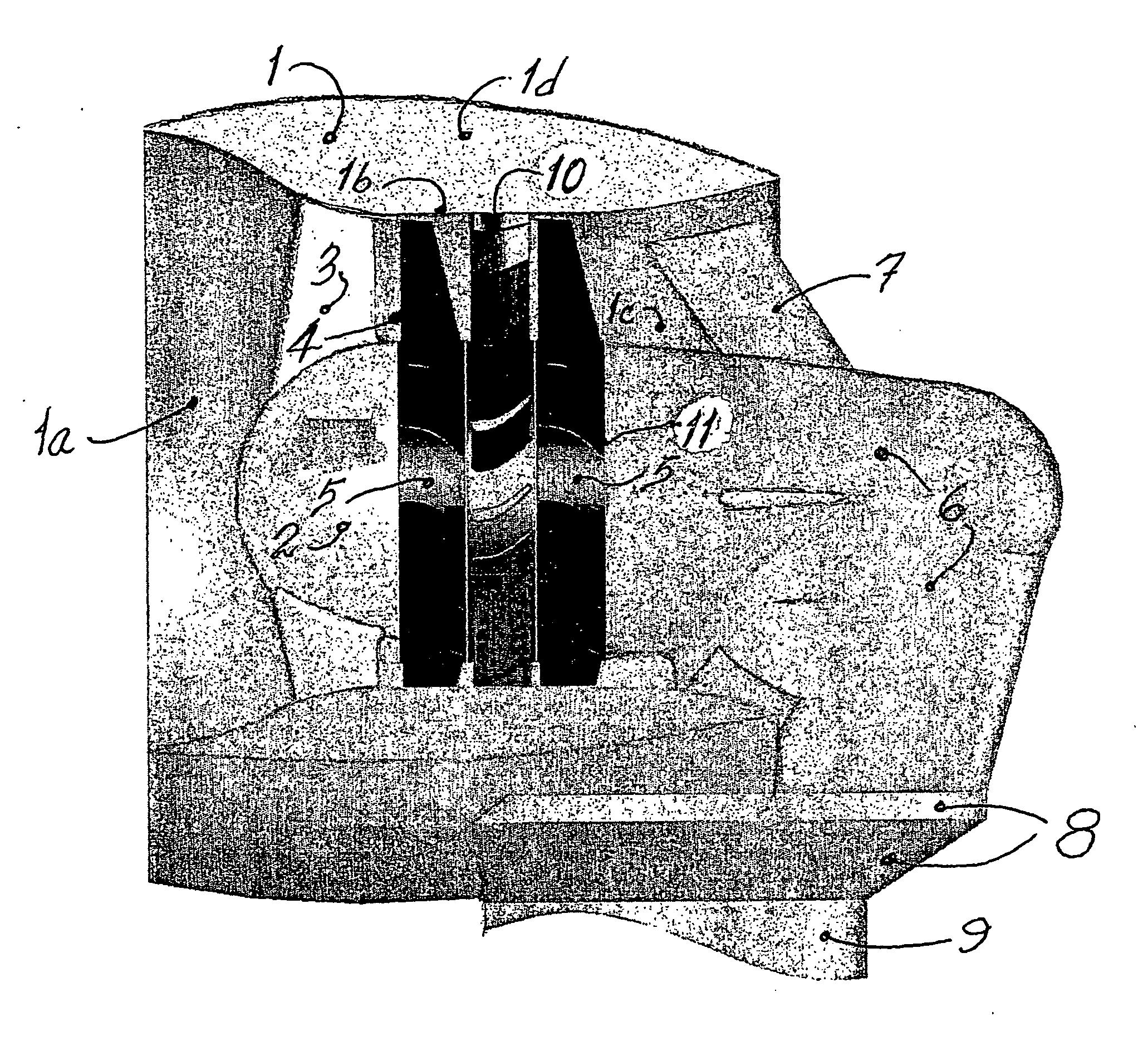
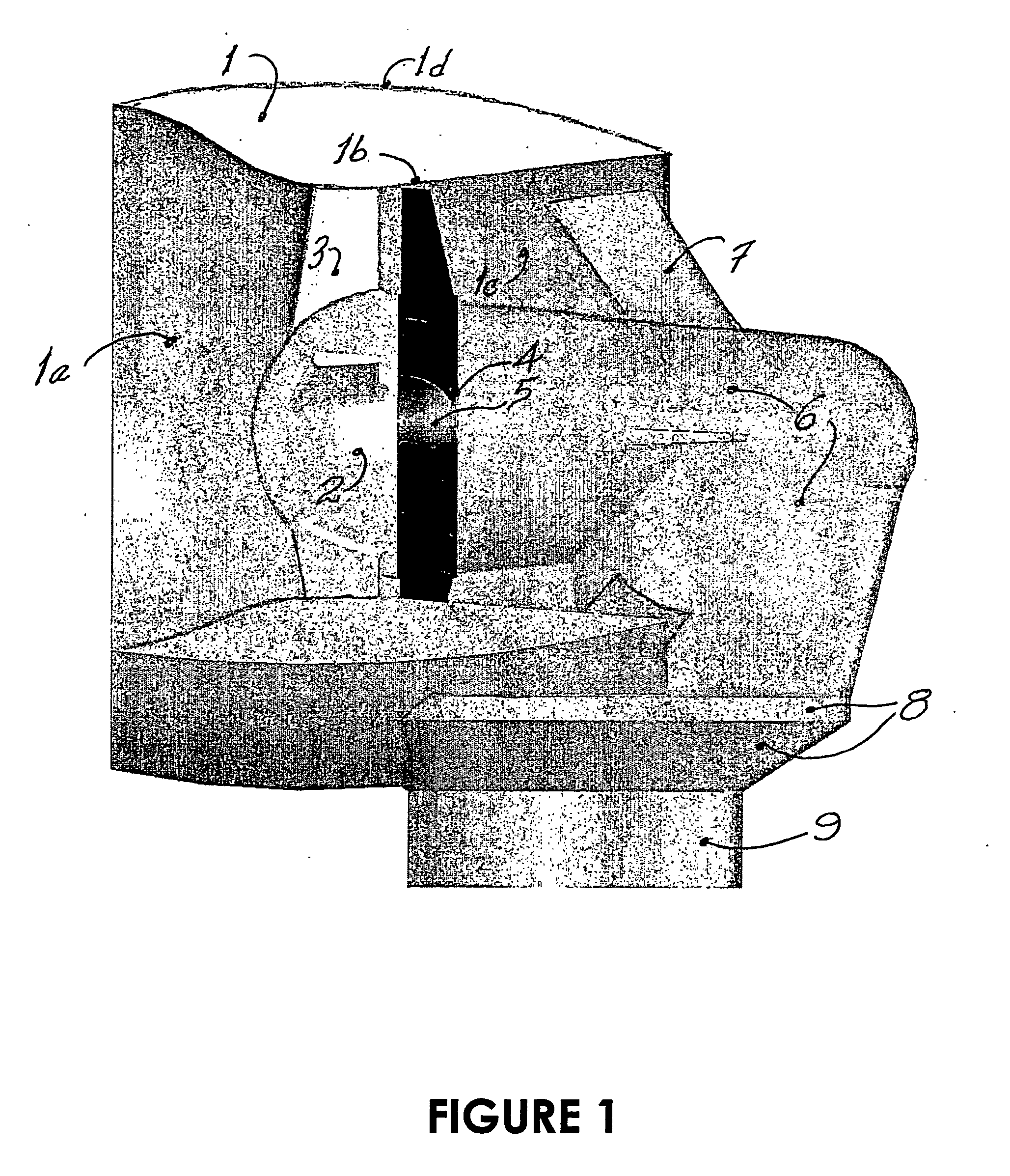
[0016]FIG. 1 is a partially cut away side view of a preferred embodiment of the invention, as mounted on the rotatable top of its support tower platform, with turbine rotor and twelve turbine blades, and with its wind intake scoop cross section cut away to show the rotor and turbine blades. Other details, being mechanical in nature, would be present state of the art, and do not need to be shown to illustrate the essential principles, details and novelty of the inventive concept.

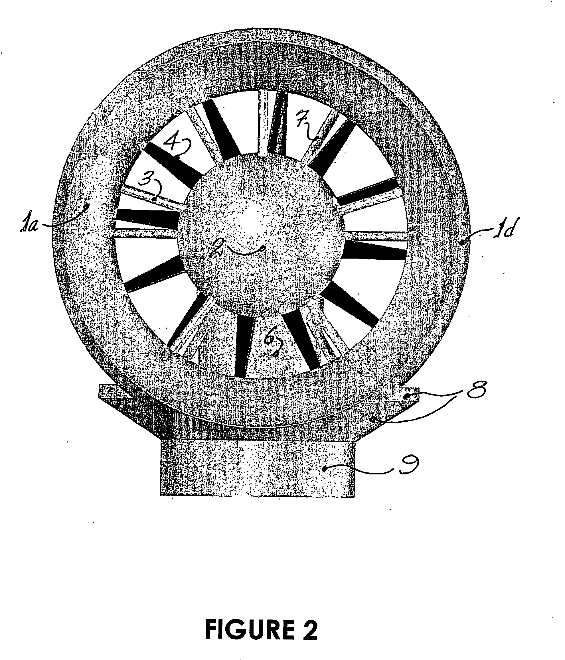
[0017]FIG. 2 is a frontal view of the same wind turbine engine embodiment, as mounted on its rotatable tower top, illustrating its wind capture area, wind intake scoop, turbine blades, and airfoil covered support and reinforcement members for the wind intake scoop and internalized axle and drive system.

[0018]FIG. 3 is a rear view of the same wind turbine engine on top of its tower mounting, as it would look directly from the rear.

[0019]FIG. 4 is a side view of the wind turbine engine, on top of its tower m...


PUM


Abstract

A wind turbine engine comprising rotor blades disposed within an outer casing and a half-spherical head located in front of the rotor blades and blocking the inner 50% of the radius of the rotor blades, the casing and head creating an acceleration chamber wherein incoming wind is speeded up and redirected around the head, and the accelerated wind then rotates the wind turbine rotor blades to generate power.

Description

BACKGROUND OF THE INVENTION [0001] The inventor has studied examples of present state of the art wind turbines of the propeller type. It was apparent that certain improvements could be made to harness a higher percentage of energy from a given cross section of wind accessed by their propeller blades. Based on principles of physics and aerodynamics known to the inventor, some serious possibilities and alternatives were apparent. At the present time, there is a growing demand for environmentally clean energy production. Costs of maintenance including the repair of weather damage to suburban and rural electrical distribution systems has reached the point where such systems are no longer profitable. This situation now provides adequate incentive toward the invention and development of more efficient and localized wind power electrical generation in the range of fifty kilowatts to one megawatt. OBJECTS OF THE INVENTION [0002] The inventor had determined that successful attainment of the ...

Claims


Application Information

Patent Timeline
IPC IPC(8): F03B15/06F03D1/00F03D1/02F03D1/04F03D80/00
CPCF03D1/025Y02E10/721F05B2240/133F03D1/04Y10S415/906Y02E10/72
Inventor JOHNSON, BUD T.J.
Owner ENVISION
Why Eureka
Try Eureka