
Liquid crystal display device

a liquid crystal display and display device technology, applied in static indicating devices, instruments, non-linear optics, etc., can solve problems such as picture quality defects, and achieve the effect of improving picture quality and reducing signal interferen

Active Publication Date: 2006-12-28
LG DISPLAY CO LTD
View PDF4 Cites 41 Cited by
  • Summary
  • Abstract
  • Description
  • Claims
  • Application Information

AI Technical Summary

Benefits of technology

The present invention is about a liquid crystal display device that improves picture quality by reducing signal interference and feed-through voltage. The invention includes a liquid crystal display panel with a plurality of data lines and gate lines, and a first and second data driver and gate driver to supply data and scan pulse to the data lines and gate lines. The technical effect of the invention is to provide a liquid crystal display with an improved picture quality that is less flicker.

Problems solved by technology

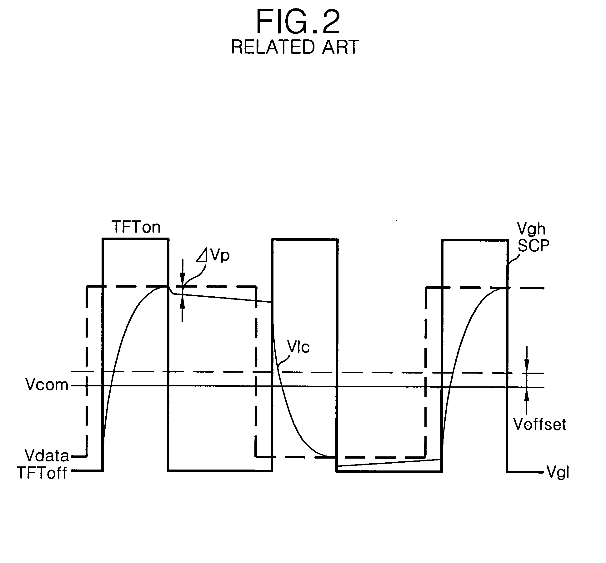
A feed through voltage deviation ΔVp within the liquid crystal display panel generated in this way becomes a cause of the flicker generation, thus the flicker and the after image become worse as the feed through voltage is higher, thereby causing a picture quality defect as a result thereof.

Method used


Image

  • Liquid crystal display device
  • Liquid crystal display device
  • Liquid crystal display device

Examples


Embodiment Construction

[0025] Reference will now be made in detail to an embodiment of the present invention, example of which is illustrated in the accompanying drawings.

[0026] With reference to FIGS. 4 to 5, embodiments of the present invention will be explained as follows.

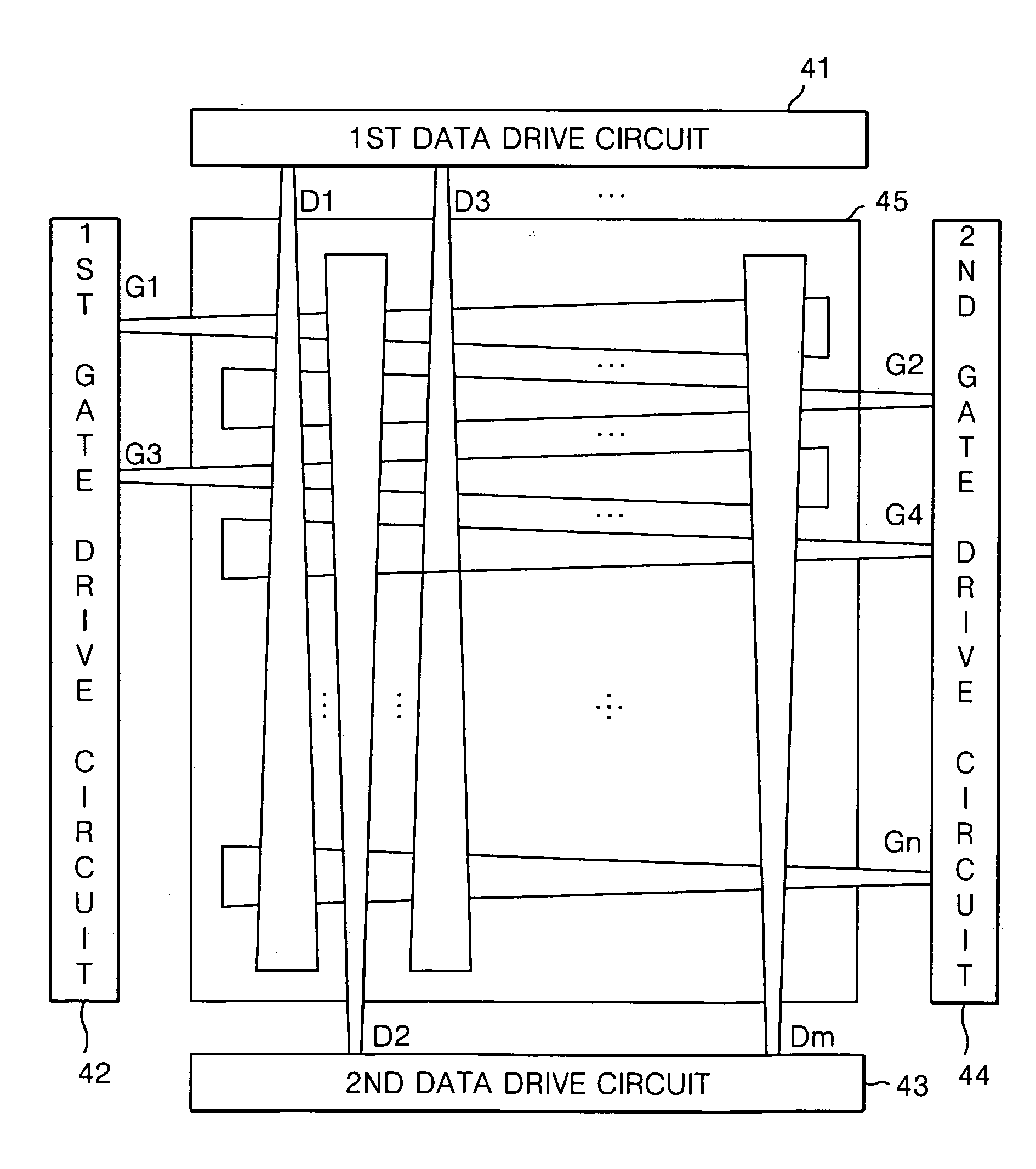
[0027]FIG. 4 is a diagram representing a liquid crystal display device according to the present invention.

[0028] Referring to FIG. 4, the liquid crystal display device according to the present invention includes first and second drive circuits 41, 43 and first and second gate drive circuits 42, 44. The first data drive circuit supplies data to an odd-numbered data line, and the second data drive circuit supplies a data to an even-numbered data line. The first gate drive circuit supplies a scan pulse to an odd-numbered gate line, and the second gate drive circuit supplies a scan pulse to an even-numbered gate line. The data lines D1, to Dm and the gate lines G1 to Gn are respectively connected to the data drive circuit and the gate ...


PUM

PropertyMeasurementUnit
resistanceaaaaaaaaaa
widthaaaaaaaaaa
lengthaaaaaaaaaa

Abstract

A liquid crystal display device according to an embodiment of the present invention includes a liquid crystal display panel which has a plurality of data lines, a plurality of gate lines crossing the data lines, and a plurality of liquid crystal cells that are defined by the data lines and the gate lines; a first data driver disposed at an upper side of the liquid crystal display panel to supply data to odd-numbered data lines; a second data driver disposed at a lower side of the liquid crystal display panel to supply data to even-numbered data lines; a first gate driver disposed at a left side of the liquid crystal display panel to supply a scan pulse to odd-numbered gate lines; and a second gate driver disposed at a right side of the liquid crystal display panel to supply a scan pulse to even-numbered gate lines, and wherein at least any one of the data lines and the gate lines has a line width that varies along its length.

Description

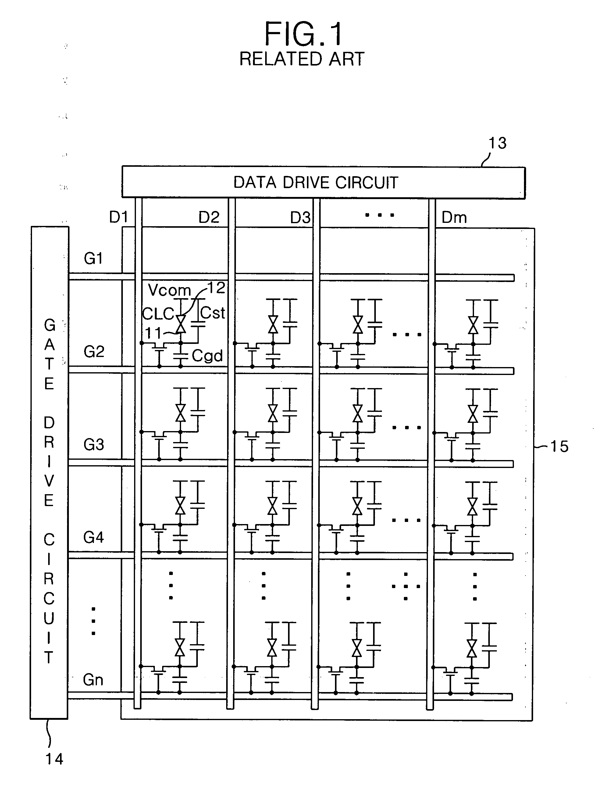
[0001] This application claims the benefit of Korean Patent Application No. P2005-55976 filed on Jun. 27, 2005, which is hereby incorporated by reference for all purposes as if fully set forth herein. BACKGROUND OF THE INVENTION [0002] 1. Field of the Invention [0003] The present invention relates to a liquid crystal display device, and more particularly to a liquid crystal display device that improves picture quality by reducing a feed-through voltage and signal interference. [0004] 2. Discussion of the Related Art [0005] Generally, a liquid crystal display device controls a light transmittance of a liquid crystal by use of an electric field, thereby displaying a picture. The liquid crystal display device includes a liquid crystal display panel where liquid crystal cells are arranged in a matrix and a drive circuit to drive the liquid crystal display panel. [0006] A liquid crystal display device of the related art, as shown in FIG. 1, includes data lines D1 to Dm and gate lines G1 ...

Claims


Application Information

Patent Timeline
Patent Type & Authority Applications(United States)
IPC IPC(8): G02F1/1343
CPCG02F1/136286G02F1/133
Inventor KO, JEONG HOONCHOI, WOON SUB
Owner LG DISPLAY CO LTD
Learn More