
Portable infrared camera

a portable, infrared technology, applied in the field of infrared thermography, can solve the problems of operator fatigue, operator inability to take dangerous or even impossible positions, infrared cameras are quite bulky and difficult to maneuver, etc., and achieve the effect of convenient camera us

Inactive Publication Date: 2006-12-28
SOFRADIR EC
View PDF12 Cites 59 Cited by
  • Summary
  • Abstract
  • Description
  • Claims
  • Application Information

AI Technical Summary

Benefits of technology

[0009] The infrared camera is designed to instantly visualize the thermal radiation of various electronic components, assemblies, mechanical systems and the like. It offers thermal imaging, precision, non-contact temperature measurement, and in-field image storage, utilizing various input devices associated with the camera. The present invention would allow thermographers to highlight and analyze problems, store images, and share results with colleagues in the field, lab, or on the factory floor. Images captured in the field can be easily transferred to a computer via the appropriate wired or wireless interface or removable media.
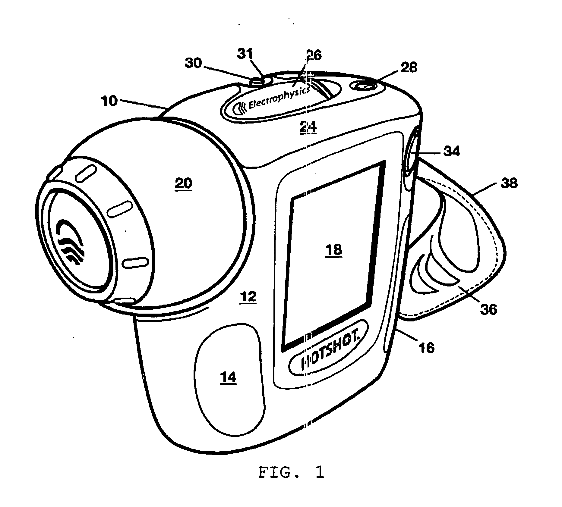
[0013] A strap is attached to the exterior surface of the camera, thereby allowing ease of use of the camera by the operator. The operator can, by employing the thumb and / or fingers of one hand, control the operation of the 5-way switch as well as the trigger for capturing images. The display screen could also operate as a touch screen utilizing the operator's hand or, an input device, such as a stylus.

Problems solved by technology

When initially developed, these infrared cameras were quite bulky and were difficult to maneuver.
Units with fixed viewing angles would potentially cause the operator fatigue, forcing the operator to assume dangerous or even impossible positions, while taking readings of a particular surface of an object under test.

Method used


Image

  • Portable infrared camera
  • Portable infrared camera
  • Portable infrared camera

Examples


Embodiment Construction

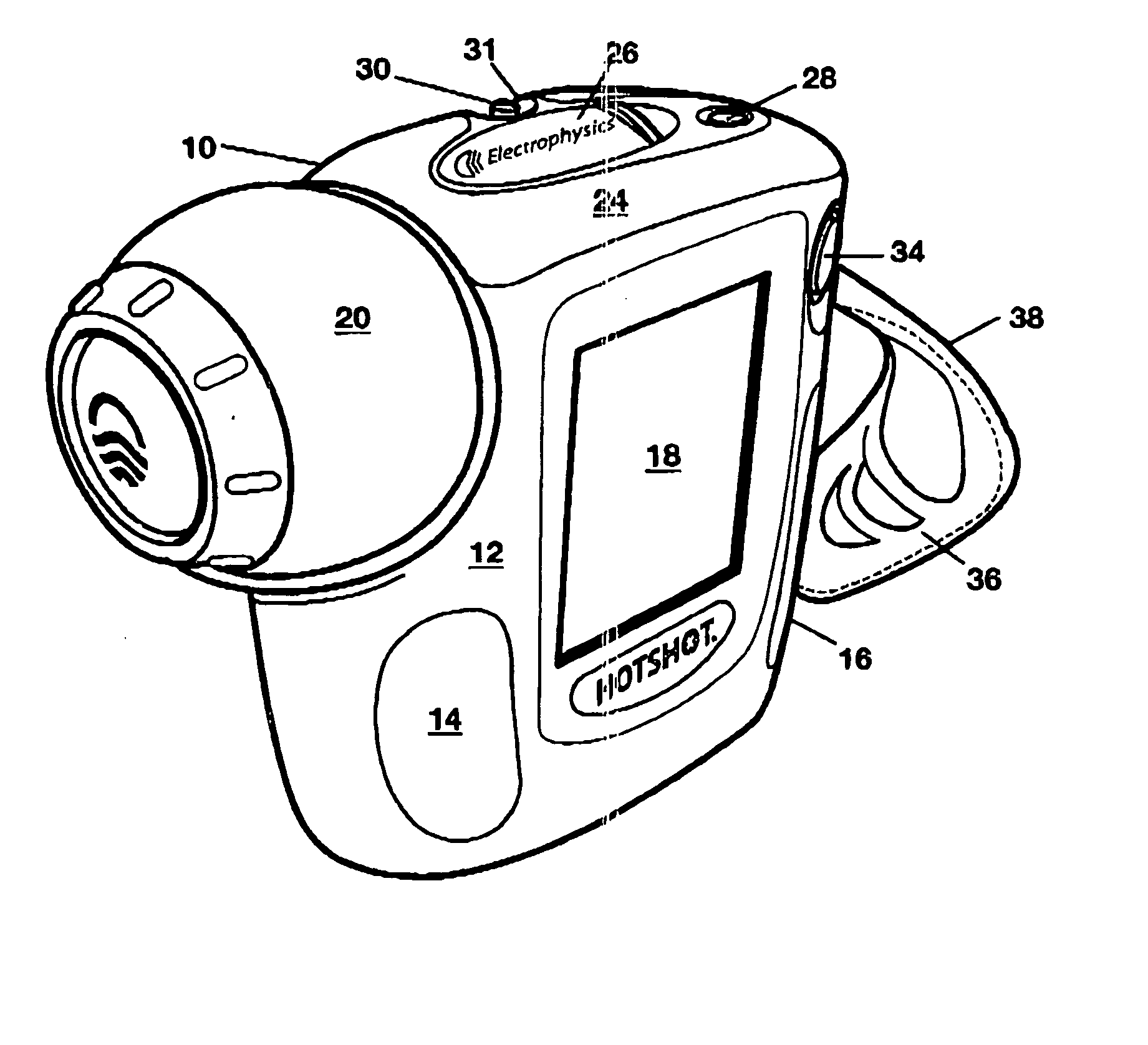
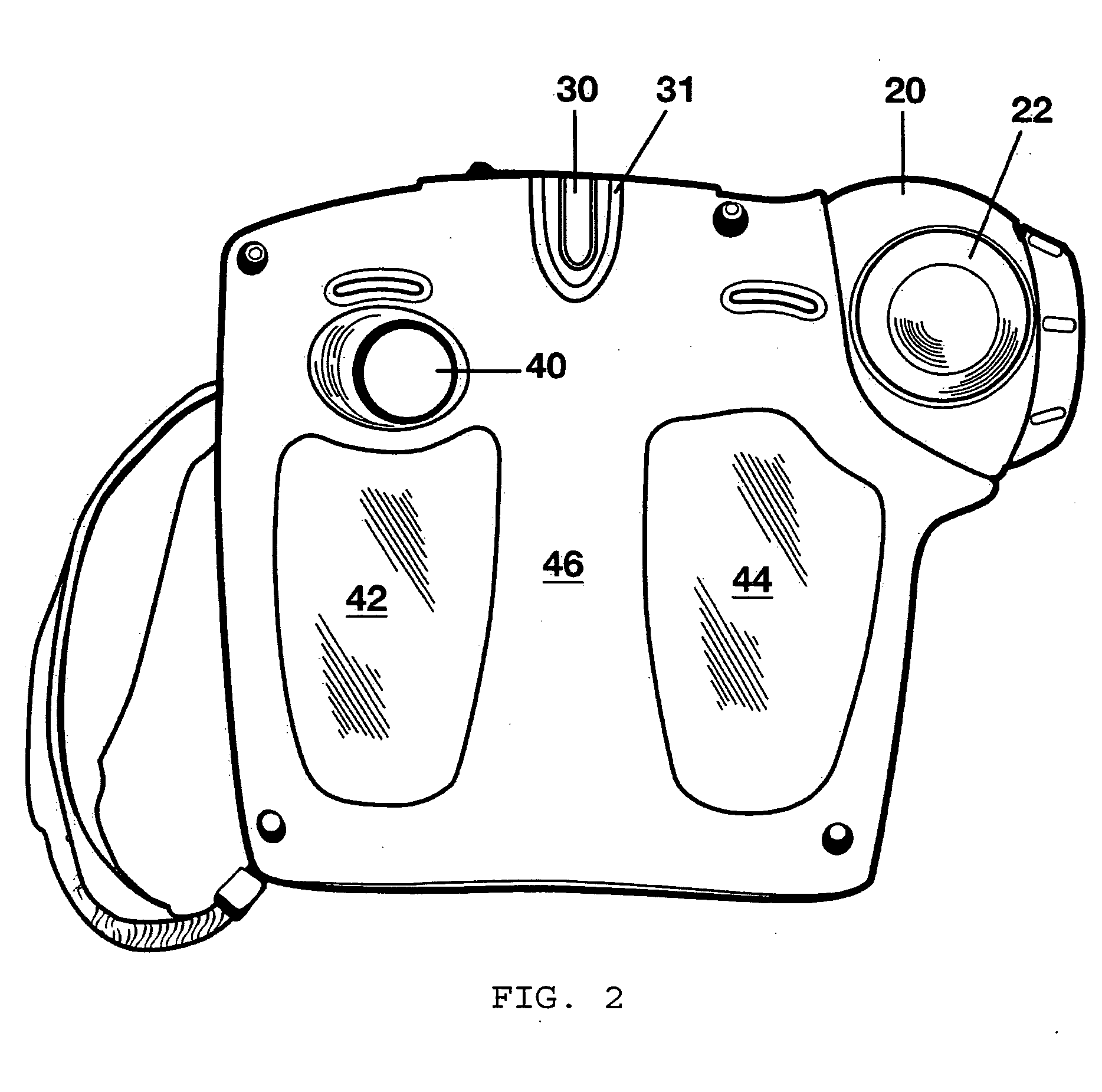
[0028] The exterior features of the infrared camera 10 are illustrated particularly with respect to FIGS. 1-7. The exterior surfaces of the camera including front and back surfaces 12 and 46, top surface 24, bottom surface 52 and side surfaces 48 and 50 may be manufactured from any hard, durable material, such as plastic.

[0029] The camera 10 is provided with a lens system 22 provided within a rotatable camera eyeball 20, allowing the lens system 22, which could include more than one lens element, to be moved from the position shown in FIGS. 1-3 to a position in which a side portion of the housing 15 (see FIG. 3) would cover the lens system 22 when the infrared camera 10 is not in use (the lens “parked” position). A digital display screen with an integrated touch panel 18 is provided on one of the side surfaces, such as surface 12 of the infrared camera. Any type of display commonly utilized in this field, such as liquid crystal display could be utilized to produce the visual effect...


PUM


Abstract

An infrared camera provided with a rotating lens. The exterior of the camera is also provided with a touch screen display as well as a switch device such as a 5-way switch, controlling many of the functions of the infrared camera. The rotation of the lens would allow an operator to view different objects while maintaining a single position, allowing the operator to view the material projected on the display very easily. A trigger would be used to capture a particular infrared image and to save this image as well as to transmit it, at a later time, to a personal computer.

Description

CROSS-REFERENCED APPLICATION [0001] The present invention claims the benefit of the priority date of U.S. Provisional Patent Application Ser. No. 60 / 673,802, filed Apr. 22, 2005.FIELD OF THE INVENTION [0002] The present invention is generally related to the field of infrared thermography. BACKGROUND OF THE INVENTION [0003] All surfaces emit thermal radiation. At a given surface temperature, there is a maximum amount of radiation that any surface can emit. If the surface emits this maximum amount of radiation, it is known as a blackbody. Most surfaces are not blackbody emitters, and emit some fraction of the amount of thermal radiation that a blackbody would emit. This fraction is known as the emissivity. For example, if a surface emits half as much radiation at a given wavelength and temperature as a blackbody, it is said to have an emissivity of 0.5. By this definition, a blackbody has an emissivity of 1.0 at all temperatures and wavelengths. [0004] Prior art portable thermal imagi...

Claims


Application Information

Patent Timeline
IPC IPC(8): G01J5/02
CPCG01J5/02H04N5/33G01J5/0215G01J5/025G01J5/026G01J5/0265G01J5/028G01J5/04G01J5/047G01J5/048G01J5/08G01J5/0806G01J5/0843G01J5/0859G01J5/089G01J2005/0077G01J2005/0081H04N5/2252H04N5/2259H04N5/23216G01J5/0205G01J5/48G01J5/07H04N23/58H04N23/51H04N23/62H04N23/20
Inventor VALLESE, FRANKARMSTRONG, JOHNDEMARCO, ROBERTDITARANTO, GERARDLAGROTTA, JAMESSTOUT, ARTWALSH, RONALD
Owner SOFRADIR EC
Learn More