
Float bath and float forming method

Inactive Publication Date: 2006-12-28
ASAHI GLASS CO LTD
View PDF4 Cites 11 Cited by
  • Summary
  • Abstract
  • Description
  • Claims
  • Application Information

AI Technical Summary

Benefits of technology

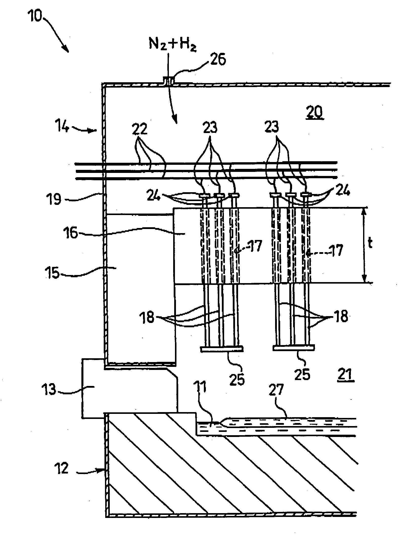
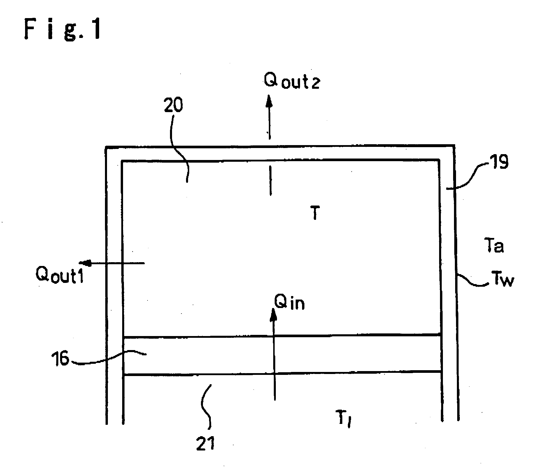
[0018] When T almost exceeds 300° C., usually a volume flow rate Vg (hereinafter referred to as Vg) of atmospheric gas (typically a mixed gas of nitrogen and hydrogen) is increased. Here, the atmospheric gas is introduced through a hole provided in e.g. an upper face of the roof casing into the upper space, and cools e.g. electric wiring components, and introduced through holes of the roof brick layer into the lower space to prevent oxidation of molten tin.
[0020] Recently, the size of glass substrates for TFT-LCD has been increased, and demand for high quality has been increased. However, the above-mentioned increase of top speck reduces production efficiency, in particular, production efficiency of large-sized above-mentioned substrates.
[0046] According to the present invention, it becomes possible to float-form such a high-viscosity glass that extremely shortens the equipment lifetime or significantly increases a risk of generating or increasing top speck when the glass is float-formed by using a conventional float bath, without increasing such a risk.

Problems solved by technology

Namely, cost for float glass manufacturing equipment including a float bath is huge, and a production stop due to a trouble after start of production causes a huge loss.

Method used


Image

  • Float bath and float forming method
  • Float bath and float forming method
  • Float bath and float forming method

Examples


example

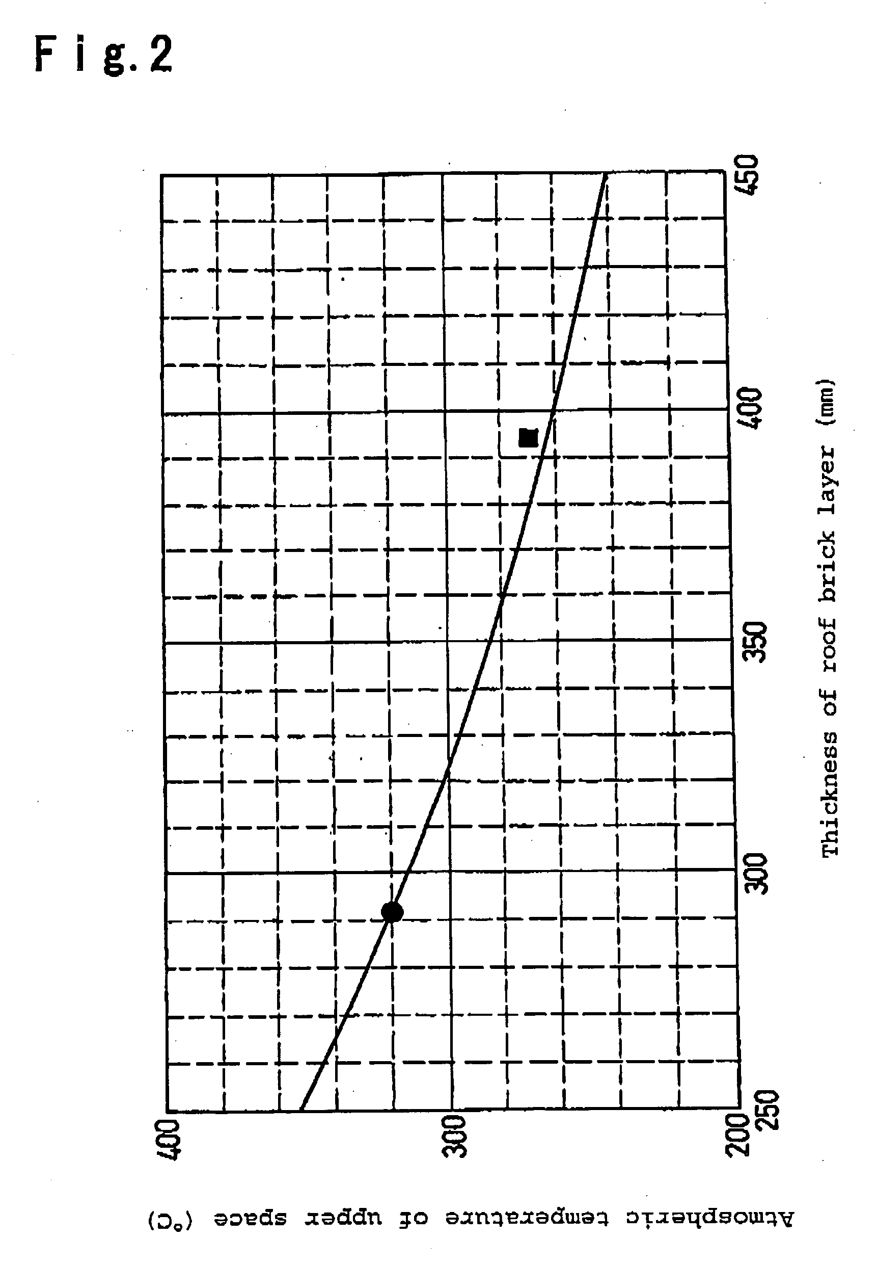
[0088] AN100 is float-formed by employing a float bath (thickness t of roof brick layer: 394 mm; a gap gAV between an inner face of a hole of roof brick layer and a heater inserted in the hole, that is averaged in a circumferential direction: 9 mm) of the present invention.

[0089] When the volume flow rate Vg of the atmospheric gas is set to be 95% of Vg by which T became 320° C. at a time of float forming AN100 in the float bath (t: 292 mm, gAV; 9 mm) employed for float-forming the above AN635, T became 270° C. (black square in FIG. 2). Since Vg is reduced, generation of top speck was suppressed and no significant reduction of equipment lifetime due to strap damage, was observed.


PUM

PropertyMeasurementUnit
Temperatureaaaaaaaaaa
Thicknessaaaaaaaaaa
Diameteraaaaaaaaaa

Abstract

A float bath and a float-forming method is provided, which can form a glass having high forming temperature without shortening the lifetime of straps for supplying electricity to heaters. A float bath 10 has a bottom 12 filled with molten tin 11, and a roof 14 for covering the bottom 12. A space in the roof 14 is separated into an upper space 20 and a lower space 21 by a roof brick layer 16, and heaters 18 are disposed through holes 17 formed in the roof brick layer 16. The thickness of the roof brick layer 16 is at least 320 mm.

Description

TECHNICAL FIELD [0001] The present invention relates to a float bath and a float forming method suitable for float-forming a glass whose viscosity becomes 104 poise at a temperature (hereinafter this temperature is referred to as forming temperature) higher than that of soda lime silica glass. BACKGROUND ART [0002] Heretofore, glass sheets produced by float-forming soda lime silica glass in a molten state, has been widely used for window glasses of e.g. buildings and automobiles, glass substrates for STN liquid crystal displays and the like. [0003] The method of float-forming soda lime silica glass in a molten state, was invented by an employee of Pilkington plc of United Kingdom in 1952, industrialized in 1959 and licensed for glass sheet manufacturers over the world thereafter. As a result, the number of facilities (float bath) for producing soda lime silica glass sheets by float-forming became at least 150 in 1996, and float-forming is a main production method for soda lime silic...

Claims


Application Information

Patent Timeline
IPC IPC(8): C03B18/02C03B13/00C03B18/00C03B18/16C03B18/22
CPCC03B18/22C03B18/16Y02P40/57
Inventor KAMIHORI, TORUMUKAI, TAKASHIKAGAMI, TOKUHIRO
Owner ASAHI GLASS CO LTD
Learn More