Scanning display
a display and scanning technology, applied in the field of scanning displays, can solve the problems of difficult manufacturing, uncomfortable feeing, and recorded noise, and achieve the effect of reducing the noise of scanning devices
- Summary
- Abstract
- Description
- Claims
- Application Information
AI Technical Summary
Benefits of technology
Problems solved by technology
Method used
Image


Examples
first embodiment
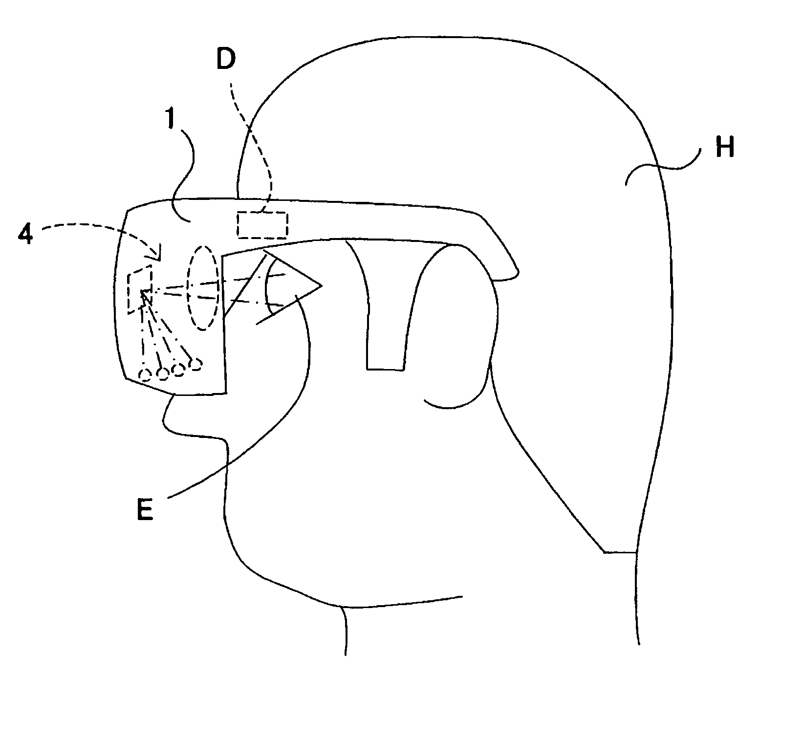
[0025]FIG. 1 shows a schematic structure of a scanning display according to a first embodiment of the present invention. The scanning display is used for a head mount display that is attached to a viewer's head and enables him to view motion and still images. Alternatively, the scanning display may be mounted as electronic viewfinder in a video camcorder and a digital camera.
[0026] In FIG. 1, 101a to 101d denote light sources, such as an LED, a laser diode, and a lamp. 102 denotes a scanning device (or a scanner) that scans the lights from the light sources 101a to 101d in two-dimensional directions. The scanning device of this embodiment includes a rotatable plane mirror. 109 denotes an ocular optical system (eyepiece) that magnifies a beam to be scanned by the scanning device 102, and introduces the beam to a viewer's eye or retina 107.
[0027] For simplified description, FIG. 1 omits an optical system that converts a divergent light from the light source into an approximately col...
second embodiment
[0063] In the second embodiment of the present invention, the horizontal view angle Fov is 24°, the horizontal resolution Res is 800 pixels, and the number Z of the partial scanning areas is 12 in the horizontal direction. The scanning display is configured similar to that of the first embodiment (FIG. 1), and common elements are designated by the same reference numerals as those in the first embodiment.
[0064] In this embodiment, the low-speed scanning direction is the horizontal direction. In the low-speed scanning direction, the scanning device 102 is driven in a sine waveform. The constant a is 2.5 (time use efficiency k=0.8), and the frequency FR is 120 Hz.
[0065] Then, the scanning frequency Freq in the high-speed scanning direction (perpendicular direction) is expressed as Freq=(α×Res×FR)×10−3 / (2×Z)=10 (kHz), and satisfies the equation (1). Thus, the noise from the high-speed scanning of the scanning device 102 has a frequency less audible to the human. In order to make the f...
third embodiment
[0068] The third embodiment of the present invention discusses a scanning display that sets, similar to the first embodiment, a low-speed scanning direction to the horizontal direction, and the number of pixels in the low-speed scanning direction to 2,160 pixels. Since the minimum resolution of the human eye is about 1 minute, the minimum resolution of the human eye accords with a size of one pixel when the horizontal view angle is 36°. Accordingly, this embodiment sets the horizontal view angle (or the entire angular field of view in the low-speed scanning direction) to 36°. The scanning display is configured similar to that of the first embodiment (FIG. 1), and common elements are designated by the same reference numerals as those in the first embodiment.
[0069] Assume that the number Z of partial scanning areas is 3 in the low-speed scanning direction, and the scanning device 102 is driven in a saw tooth waveform in the low-speed scanning direction. Also assume that the frequency...
PUM
 Abstract
Description
Claims
Application Information
 - R&D
- Intellectual Property
- Life Sciences
- Materials
- Tech Scout
- Unparalleled Data Quality
- Higher Quality Content
- 60% Fewer Hallucinations
Browse by: Latest US Patents, China's latest patents, Technical Efficacy Thesaurus, Application Domain, Technology Topic, Popular Technical Reports.
© 2025 PatSnap. All rights reserved.Legal|Privacy policy|Modern Slavery Act Transparency Statement|Sitemap|About US| Contact US: help@patsnap.com