
Inverted feed discone antenna and related methods

Inactive Publication Date: 2006-12-21
HARRIS CORP
View PDF12 Cites 24 Cited by
  • Summary
  • Abstract
  • Description
  • Claims
  • Application Information

AI Technical Summary

Benefits of technology

[0009] In view of the foregoing background, it is therefore an object of the present invention to provide a broadband antenna having an increased pattern bandwidth and with a less complicated feed attachment.
[0014] The discone antenna with such an inverted feed structure according to the present invention is less expensive to make in view of the elimination of the feed connection within the cone, and because of the use of conventional flanged coaxial connectors. Furthermore, the antenna facilitates an inverted positioning, for example, on vehicles, rooftops and / or control towers, etc., that will increase the radiation pattern bandwidth in the direction of the target. The discone antenna may also be used in an upright position in a ceiling, for example, for wireless local area network (WLAN) systems.

Problems solved by technology

The simple ½ wave wire dipole antenna, which can have 2.0 to 1 VSWR bandwidth of only 4.5 percent, is often not adequate.
These antennas, however, are sometimes expensive or difficult to manufacture.
This may be undesirable for various applications.
Furthermore, the attachment of the antenna feed is complicated due to the routing through the cone.

Method used


Image

  • Inverted feed discone antenna and related methods
  • Inverted feed discone antenna and related methods
  • Inverted feed discone antenna and related methods

Examples


Embodiment Construction

[0020] The present invention will now be described more fully hereinafter with reference to the accompanying drawings, in which preferred embodiments of the invention are shown. This invention may, however, be embodied in many different forms and should not be construed as limited to the embodiments set forth herein. Rather, these embodiments are provided so that this disclosure will be thorough and complete, and will fully convey the scope of the invention to those skilled in the art. Like numbers refer to like elements throughout, and prime notation is used to indicate similar elements in alternative embodiments.

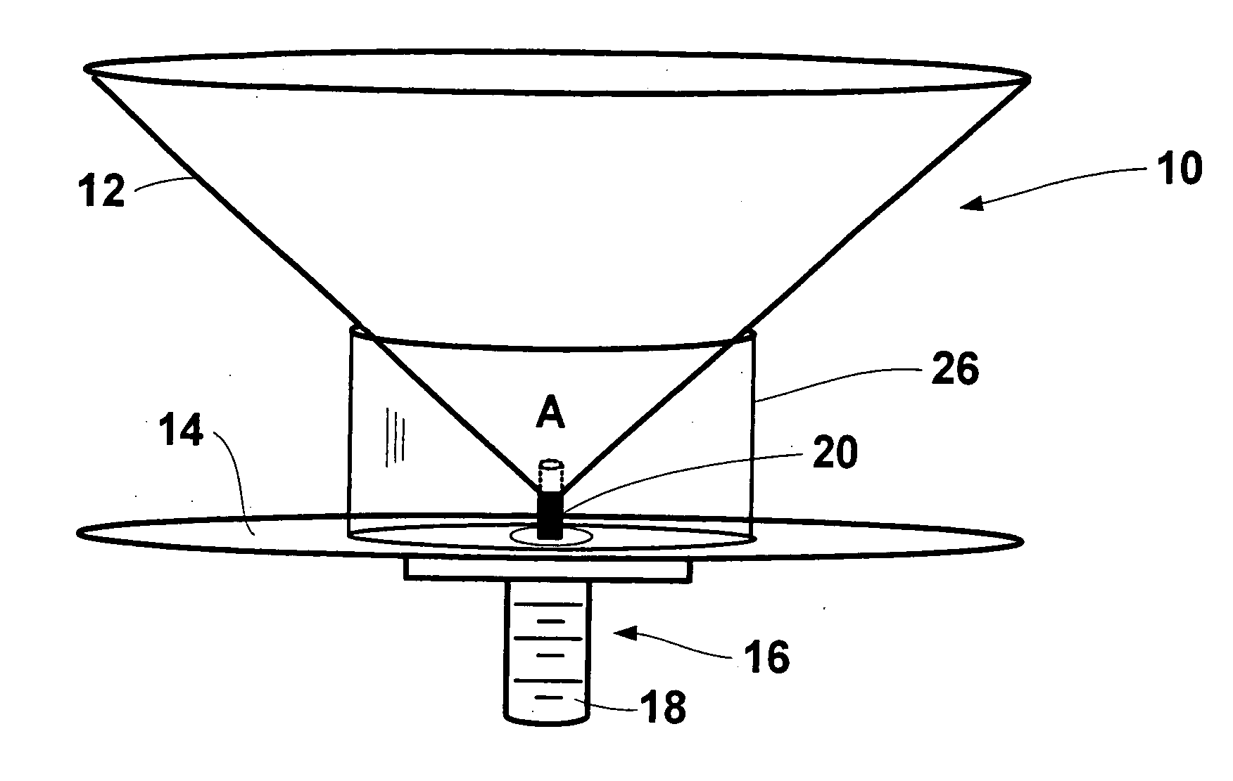
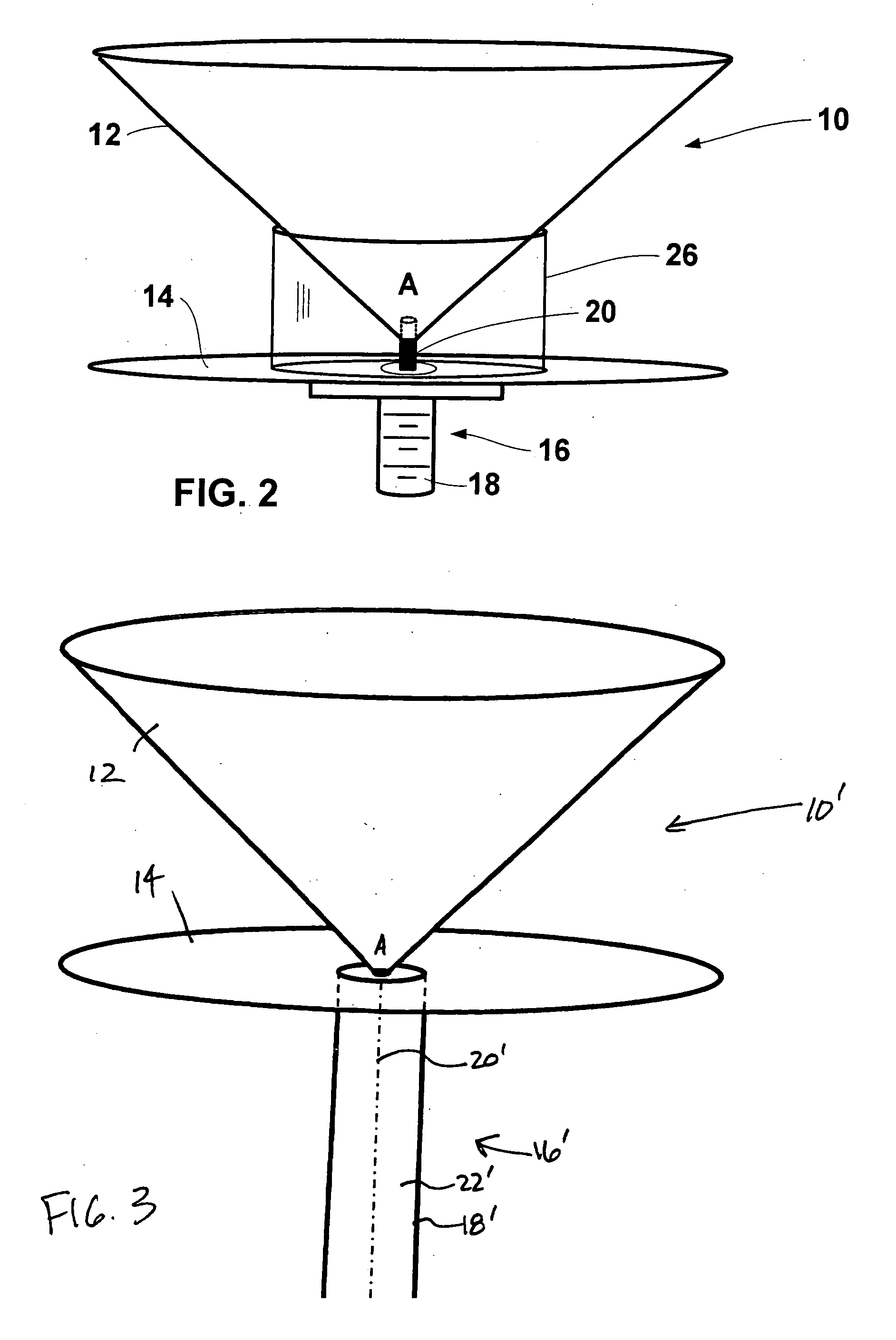
[0021] Referring initially to FIG. 2, a discone antenna 10 according to the present invention will now be described. The discone antenna 10 includes a conical antenna element 12, having an apex A, and a disc antenna element 14 adjacent the apex of the conical antenna element. The conical antenna element 12 and / or the disc antenna element 14 may comprise a continuous condu...


PUM


Abstract

The discone antenna includes a conical antenna element, having an apex, and a disc antenna element adjacent the apex of the conical antenna element. An inverted antenna feed structure, such as a flanged coaxial connector or coaxial cable, is connected to the disc and conical antenna elements and extends outwardly from the disc antenna element on a side thereof opposite the apex of the conical antenna element. The discone antenna with such an inverted feed structure facilitates an inverted positioning, for example, on vehicles, rooftops and / or control towers, etc., that will increase the bandwidth pattern in the direction of the potential target.

Description

FIELD OF THE INVENTION [0001] The present invention relates to the field of antennas, and more particularly, this invention relates to low-cost broadband antennas, omnidirectional antennas, and related methods. BACKGROUND OF THE INVENTION [0002] Modern communications systems are ever more increasing in bandwidth, causing greater needs for broadband antennas. The simple ½ wave wire dipole antenna, which can have 2.0 to 1 VSWR bandwidth of only 4.5 percent, is often not adequate. Broadband dipoles are an alternative to the wire dipole. These preferably utilize cone radiating elements, rather than thin wires. A biconical dipole, having for example, a conical flare angle of ½π radians has essentially a high pass filter response, from a lower cut off frequency. Such an antenna provides great bandwidth, and a response of 10 or more octaves is achieved. [0003] Wire dipoles can be easily constructed by various techniques, including modifications of coax cable. In one modification, shield br...

Claims


Application Information

Patent Timeline
IPC IPC(8): H01Q13/00
CPCH01Q21/29H01Q9/28
Inventor PARSCHE, FRANCIS EUGENEMALONEY, ROBERT PATRICKLAVALLEE, ROBERT NATHAN
Owner HARRIS CORP
Learn More