
Reception device and reception method

a reception device and reception method technology, applied in the field of reception apparatus and reception method, can solve the problems of channel not being obtained, multi-path fading, and comparable spreading gain, and achieve the effect of reducing noise enhancemen

Active Publication Date: 2006-12-14
APPLE INC
View PDF5 Cites 2 Cited by
  • Summary
  • Abstract
  • Description
  • Claims
  • Application Information

AI Technical Summary

Benefits of technology

[0024] It is an object of the present invention to provide a reception apparatus and a reception method for reducing a noise enhancement produced in packet channels after equalization due to a difference between a spreading factor of a common pilot channel and a spreading factor of packet channels.

Problems solved by technology

As a result, multiplied waves interfere mutually and generate multipath fading.
However, reception apparatus has the following problems in the above-mentioned conventional.
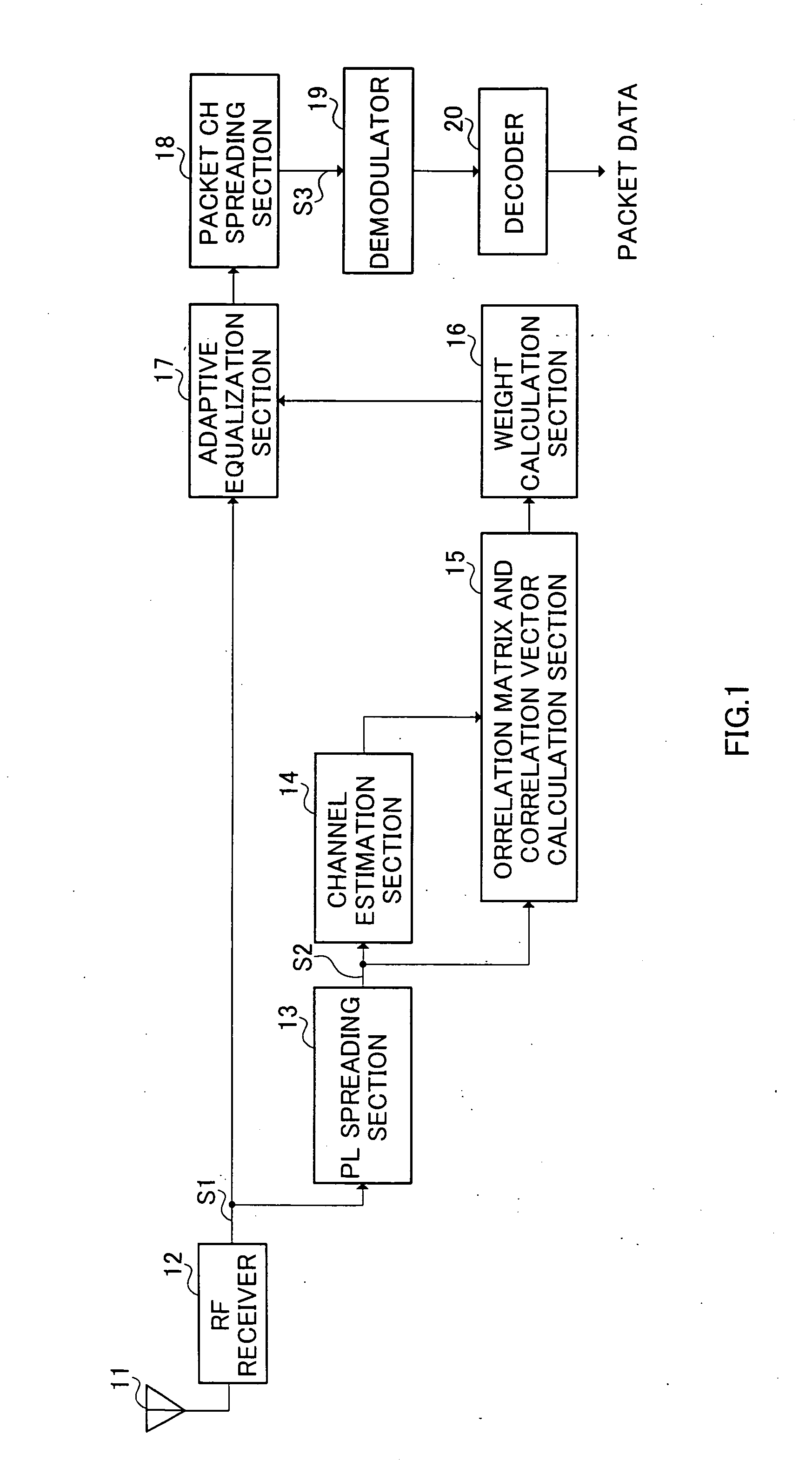
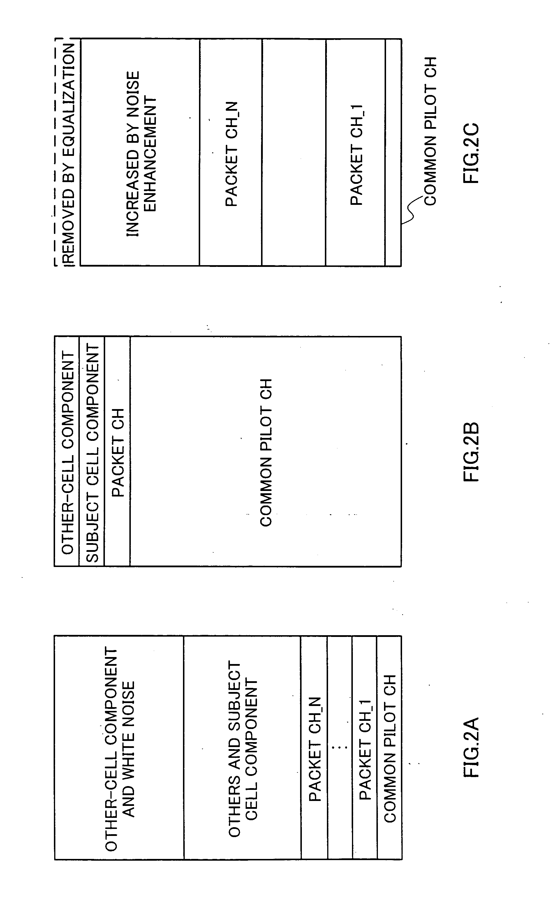
However, in the packet channels which are actual targets of equalization, since the spreading factor is lower than that of the common pilot channel, a spreading gain comparable to that of common pilot channel cannot be obtained, and noise is enhanced through operation of the adaptive equalization section.
Incidentally, under the condition that noise enhancement becomes large; the demodulation performance may be inferior to that of RAKE receiver which does not mount an adaptive equalization section in the worst case.

Method used


Image

  • Reception device and reception method
  • Reception device and reception method
  • Reception device and reception method

Examples


embodiment 1

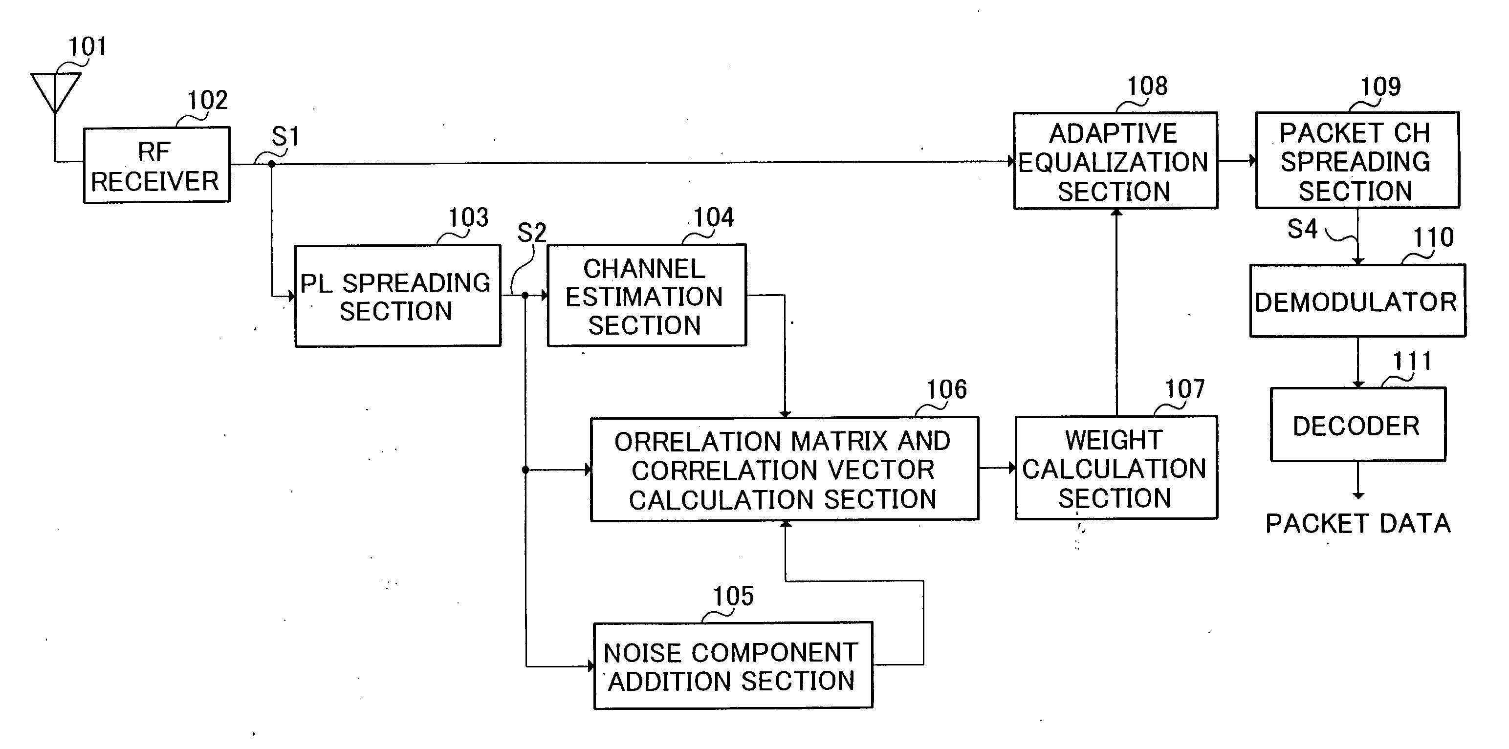
[0038]FIG. 3 is a block diagram showing a configuration of a reception apparatus in a communication terminal apparatus according to Embodiment 1 of the present invention. In this figure, antenna 101 receives signal transmitted from a base station apparatus, and outputs the received signal (reception signal) to RF receiver 102.

[0039] RF receiver 102 implements predetermined radio reception processing (a down conversion, A / D conversion and suchlike) on the reception signal and outputs the signal after radio reception processing to adaptive equalization section 108 and PL spreading section 103.

[0040] PL spreading section 103 despreads the signal outputted from RF receiver 102 using spreading code created by spreading the common pilot signal in the base station apparatus, and outputs the signal after despreading to channel estimation section 104, noise component addition section 105 and correlation matrix and correlation vector calculation section 106.

[0041] Based on the signal outpu...

embodiment 2

[0060]FIG. 5 is a block diagram showing a configuration of a reception apparatus in a communication terminal apparatus according to Embodiment 2 of the present invention. In FIG. 5, the same parts as in FIG. 3 are assigned the same reference numerals as in FIG. 3 to omit detailed explanations thereof. The difference between FIG. 5 and FIG. 3 is that in FIG. 5, minimal component removing section 301 substitutes for noise component addition section 105 in FIG. 3.

[0061] Minimal component removing section 301 evaluates the maximum value of input signal vector max (r (n)) using despreading result of input signal outputted from PL spreading section 103. Then, minimal component removing section 301 multiplies max(r(n)) by a constant relativeSNR which is dependent on spreading factor of common pilot channel and spreading factor of packet channels and calculates a noise equivalent value noise_power, using Equation (8) explained in Embodiment 1. Furthermore, minimal component removing sectio...

embodiment 3

[0066]FIG. 6 is a block diagram showing a configuration of a reception apparatus in a communication terminal apparatus according to Embodiment 3 of the present invention. In FIG. 6, the same parts as in FIG. 3 are assigned the same reference numerals as in FIG. 3 to omit detailed explanations thereof. The difference between FIG. 6 and FIG. 3 is in that in FIG. 6, inter-cell interference ratio calculation section 401 is provided and noise component addition section 402 substitutes for noise component addition section 105 in FIG. 3

[0067] Inter-cell interference ratio calculation section 401 calculates estimatedCIR which is a ratio of the subject cell interference component to other-cell, interference component based on signal outputted from PL spreading section 103. More specifically, estimatedCIR is calculated from value obtained by averaging the input signal vector expressed by Equation (1) for a long time. The calculated estimatedCIR is outputted to noise component addition section...


PUM


Abstract

At noise component addition section 105, a noise equivalent value equivalent in size to noise component is calculated using a constant which is dependent on a difference of spreading factors between a common pilot channel and packet channels, and at correlation matrix and correlation vector calculation section 106, the noise equivalent value is added to diagonal elements of an autocorrelation matrix. At weight calculation section 107, an optimal weight is calculated using the autocorrelation matrix whose diagonal elements have been added the noise equivalent value, and at adaptive equalization section 108, equalization of reception signal is carried out. Thereby, noise enhancement produced in the packet channels after the equalization due to the difference between the spreading factor of the common pilot channel and the spreading factor of the packet channels can be reduced.

Description

TECHNICAL FIELD [0001] The present invention relates to a reception apparatus and a reception method for carrying out adaptive equalization in which a common pilot channel signal is used as a reference signal, and is suitable for applying to a communication terminal apparatus, for example. BACKGROUND ART [0002] Generally, multipath is formed between a base station apparatus and a communication terminal apparatus by reflection, diffraction, and / or dispersion of radio waves under the influence of buildings and suchlike. As a result, multiplied waves interfere mutually and generate multipath fading. In the HSDPA (High Speed Downlink Packet Access) scheme and suchlike known as high speed downlink packet transmission, since the modulation M-ary number for packet channels is as high as 16 QAM, reception performance will deteriorate severely by inter-path interferences resulting from the multipath fading. [0003] Then, it is possible to carry out adaptive equalization in the communication t...

Claims


Application Information

Patent Timeline
Patent Type & Authority Applications(United States)
IPC IPC(8): H04B1/00H04B1/707H04B1/7097H04B7/005
CPCH04B1/71052H04B1/71055H04B2201/70701H04L25/03019H04L25/0224H04L25/0242H04L25/025H04B2201/70702
Inventor ARIMA, TAKENOBU
Owner APPLE INC
Learn More