Second order bandpass filter

a filter and bandpass technology, applied in the field of bandpass filter, can solve the problems of poor signal reception at the receiver, affecting the efficiency of noise filtering, and unable to provide a good suppression over interference signals, etc., to achieve efficient filtering of noise, low insertion loss, and good use

Inactive Publication Date: 2006-12-14
NAT CHIAO TUNG UNIV
View PDF4 Cites 9 Cited by
  • Summary
  • Abstract
  • Description
  • Claims
  • Application Information

AI Technical Summary

Benefits of technology

[0009] It is, therefore, an object of the present invention to provide a second-order bandpass filter having an improved frequency response in which two finite zeros, a low-loss pass band are provided and through which a second harmonic frequency signal of a operating signal and GSM signals may be filtered out.
[0011] With a proper design, the second-order bandpass filter may provide two finite zeros corresponding to frequencies of between 1.8 to 1.9 GHz and between 3.6 to 4.8 GHz, a pass band having a central frequency of 2.45 GHz and a frequency bandwidth greater than 100 MHz. With such frequency response, the second harmonic frequency signal and GSM signals may be filtered out. Further, the filter features a low insertion loss with respect to the pass band, leading the filter to be well used in the wireless LAN application. In addition, frequency difference of the two zeros may be adjusted by directly varying capacitance of the grounding capacitor and thus used directly in other applications.
[0012] The present invention may at least achieve the following advantages. 1. Two finite zeros are provided and thus noises may be efficiently filtered out. 2. Frequency difference with respect to the two finite zeros may be adjusted by directly changing the grounding capacitance. 3. No component having an extremely low value is used and thus frequency response may be fixed among such filters. 4. Small volume making easy to be integrated with other components.

Problems solved by technology

However, poor frequency response may cause a poor signal reception at the receiver and even makes the signal received stultified.
Although two finite zeros are provided, they are not both corresponding to interference signals (with frequencies of 1.8 GHz, 1.9 GHz and 4.8 GHz in IEEE802.11b / g specification used in wireless LAN application) or exclude these interference signals outside the pass band and thus may not provide a good suppression over these interference signals, wherein the interference signals are generated by components such as an oscillator / mixer in a transmitter and GSM signals.
Further, second harmonic frequency signal of the operating signal can also not be efficiently filtered out (since its frequency 4.8-5 GHz may not correspond to −30 dB suppression).
Further, the used coupling capacitor C is only 0.1 μF and frequency response of the filter is thus susceptible to vary due to inaccuracy of fabrication process.
In view of this characteristic, such second-order bandpass filter is not ideal.
As a result, the aforementioned second harmonic frequency signal may not be suppressed enough and further a central band of the filter has a too large insertion loss, making the transmitted signal having an insufficient level of power.
Thus, the received signal through such filter may not achieve a satisfied quality, making the filter disqualified to be used in the wireless LAN application.

Method used


Image

  • Second order bandpass filter
  • Second order bandpass filter
  • Second order bandpass filter

Examples


Embodiment Construction

[0019] The present invention discloses a second-order bandpass filter, which will be described taken from the preferred embodiments with reference to the annexed drawings.

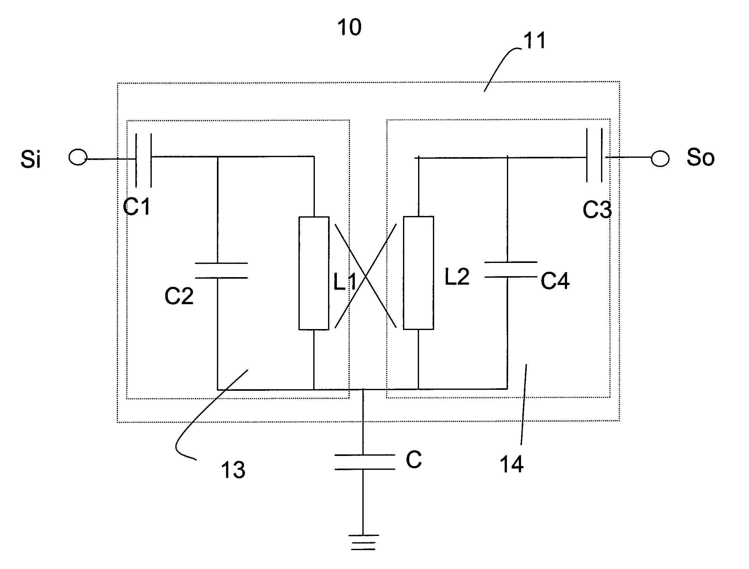
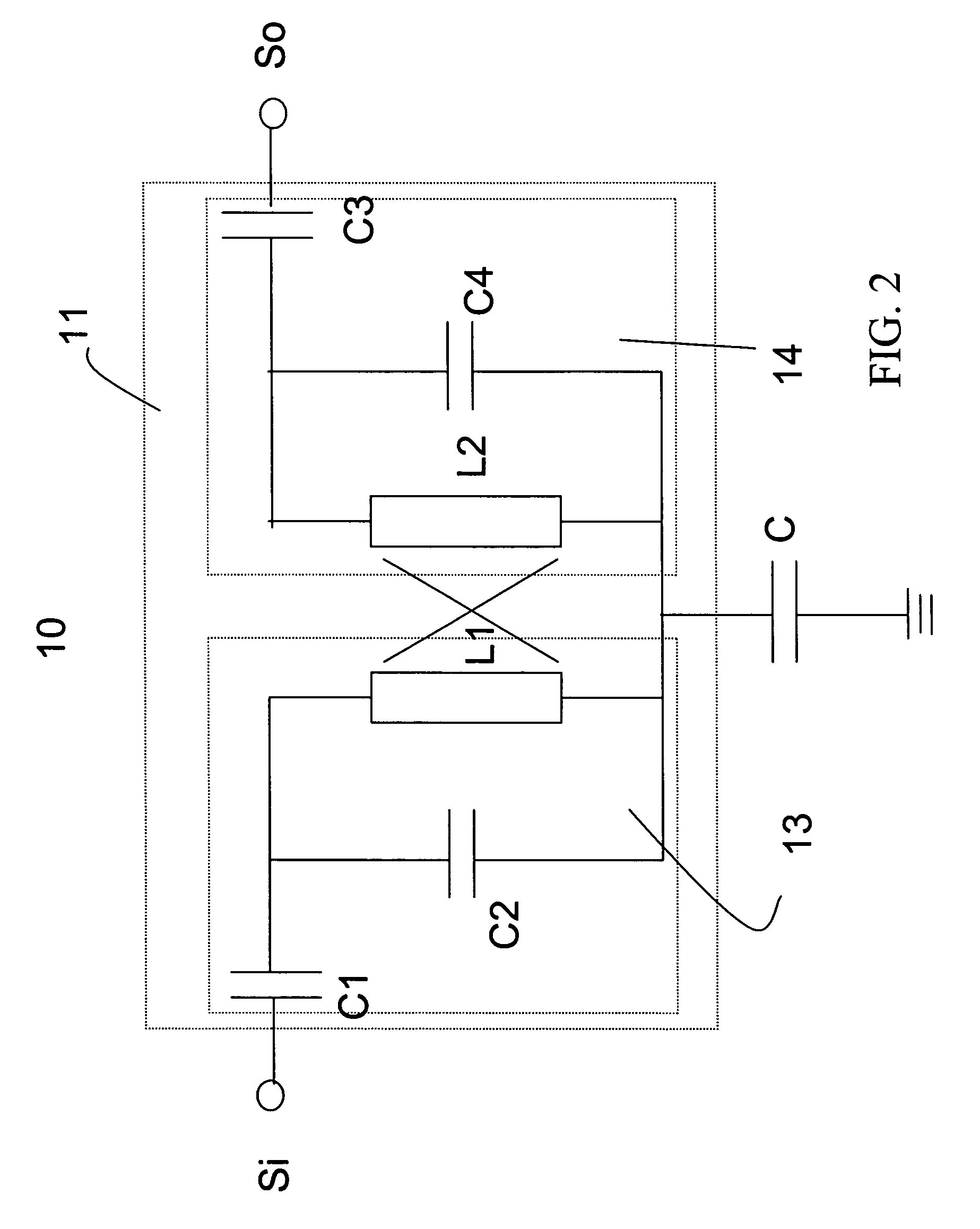
[0020]FIG. 2 shows a schematic structure diagram of a second-order bandpass filter according to the present invention. As shown, the second-order bandpass filter 10 comprises a two-port network 11 and a grounding capacitor C. The two-port network 11 comprises a first port 13 and a second port 14. An input signal Si is inputted at the first port 13 and an output signal So is outputted at the second port 14.

[0021] The first port 13 comprises a first blocking capacitor C1, a first resonance capacitor C2 and a first resonance inductor L1. The input signal Si is first inputted to the first blocking capacitor C1 at one end and a DC component thereof is filtered out. The first resonance capacitor C2 is coupled electrically to the other of the first blocking capacitor C1 at one end. The first resonance inductor L1 is cou...


PUM


Abstract

A second-order bandpass filter having an improved frequency response is disclosed, in which a grounding capacitor is connected electrically to a two-port network as a feedback path so as to provide two finite transmission zeros. With the two transmission zeros, signals of second harmonic frequency and GSM signals may be blocked out from the pass band of the filter and thus filtered out. As such, the filter may be utilized in wireless local area network (WLAN) application. Further, since no extremely small value component is used within the filter, the frequency response may not be influenced by a manufacturing process of the filter. In addition, the thus formed filter has a relatively smaller volume.

Description

BACKGROUND OF THE INVENTION [0001] 1. Field of the Invention [0002] The present invention relates to a bandpass filter. More particularly, the present invention relates to a second-order bandpass filter having an improved frequency response. [0003] 2. Descriptions of the Related Art [0004] Filter is a passive device generally used in communications, electronic and electrical fields, particularly in wireless communications field for filtering out noises so that a transmitted signal through the filter may be used by a receiver. Bandpass filter is a filter which allows only a signal whose frequency is within a specific frequency band (referred to as a pass band) to pass there through and other signals having other frequencies (referred to as a stop band), i.e. noises, are otherwise filtered out. Therefore, the bandpass filter can be indispensable to the wireless communications field. Since the band pass filter is used for noise filtering, it is expected to have a good frequency respons...

Claims


Application Information

Patent Timeline
IPC IPC(8): H03H7/01
CPCH03H7/09H03H7/1775H03H7/1725H03H7/1708
Inventor CHUNG, SHYH-JONGCHANG, CHUN-FU
Owner NAT CHIAO TUNG UNIV
Why Eureka
Try Eureka