
Method of recovering timing over a granular packet network

a timing information and packet network technology, applied in the field of packet network recovery, can solve the problems of loss of precision in timing information exchanged between the source and destination nodes, loss of precision of ctt method, and method sensitive to packet delay variation, so as to overcome the loss of precision and limit the achievable precision

Active Publication Date: 2006-11-30
ZARLINK SEMICON LTD
View PDF6 Cites 23 Cited by
  • Summary
  • Abstract
  • Description
  • Claims
  • Application Information

AI Technical Summary

Benefits of technology

[0008] The present invention overcomes the loss of precision that occurs when a time granular switching component or a synchronous series of such components put a limit on the achievable precision.
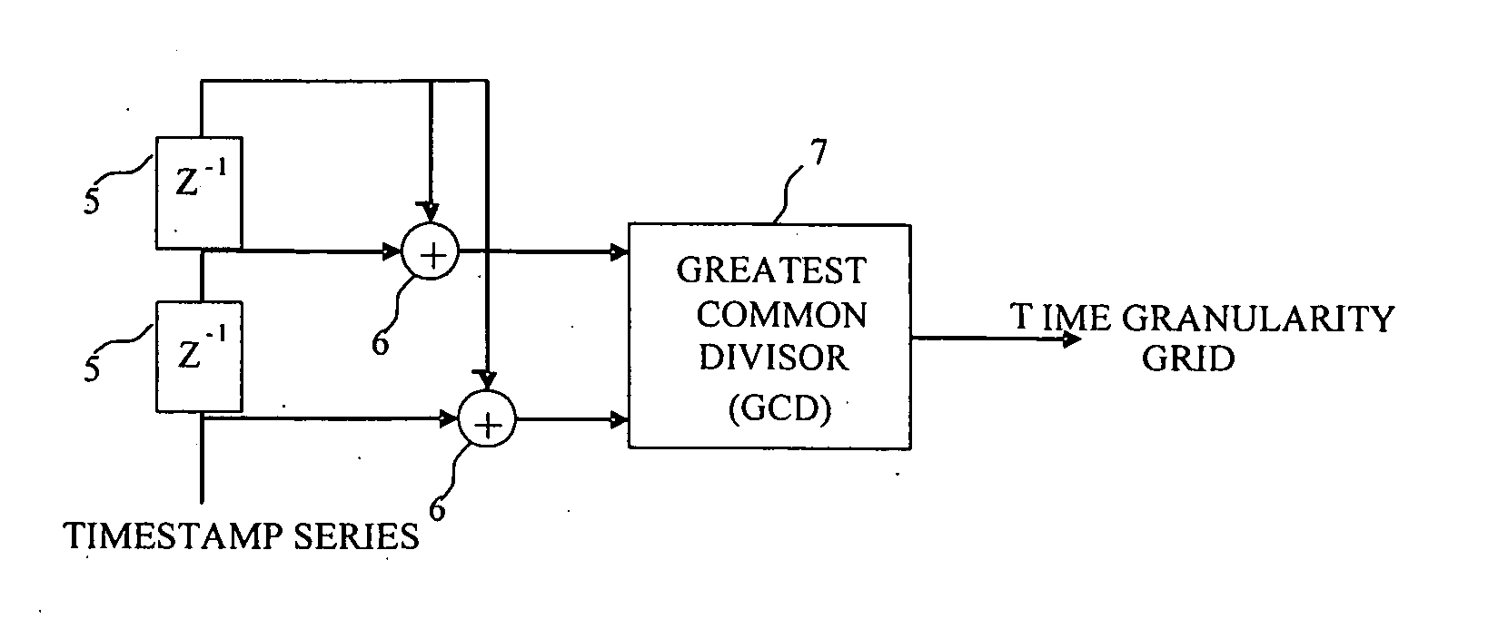
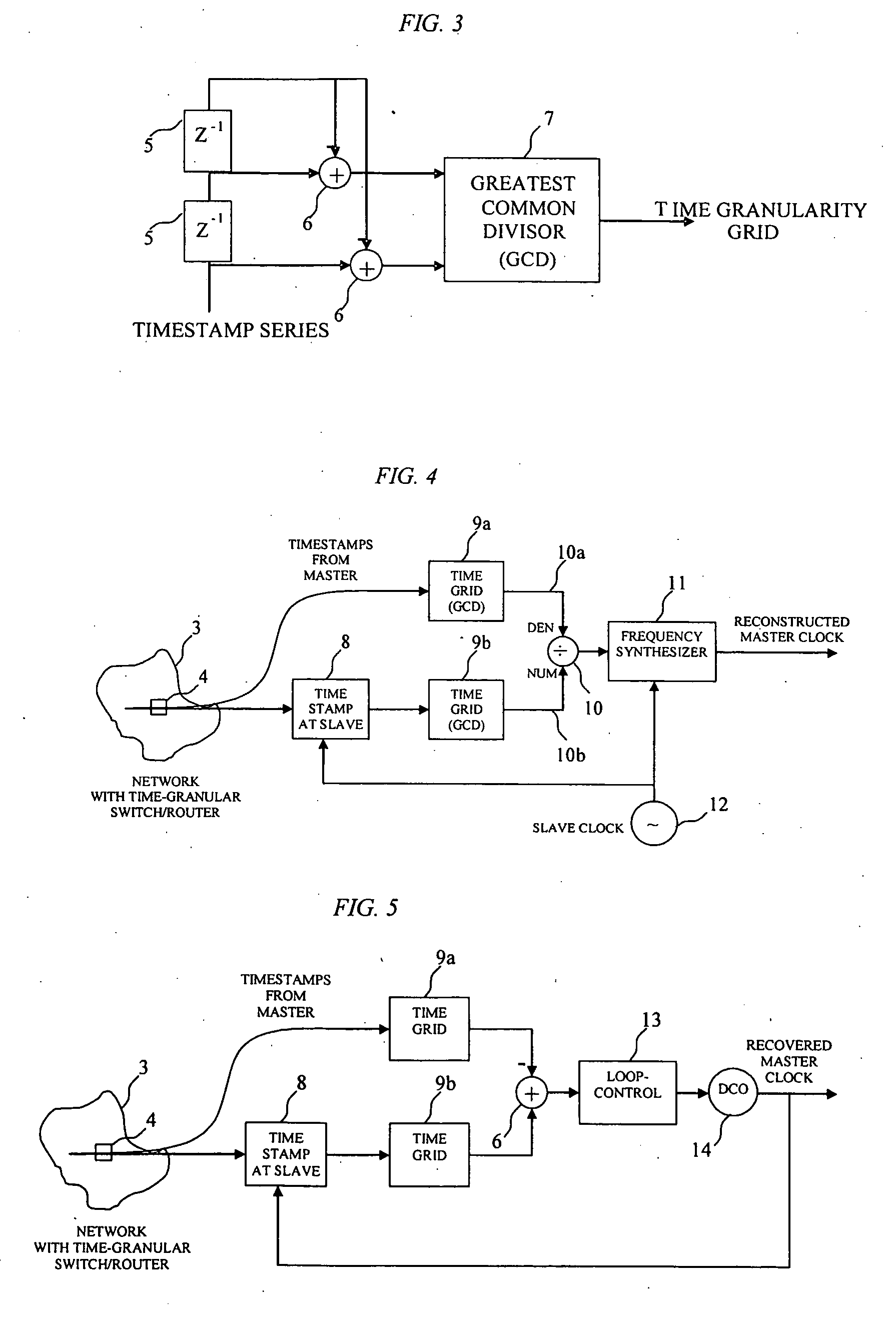
[0011] In one embodiment the granularity can be determined at the nodes receiving the packets by searching for a denominator value that provides a common remainder for a series of timestamps captured upon arrival. A frequency offset of the local slave clock creates an offset to both denominator values found at the master and the slave. The system uses the found offset to adjust the slave clock frequency or to generate a new clock from the slave clock using frequency synthesis techniques. The system can be used in combination with existing time synchronization techniques to improve the precision.
[0015] Drift can also degrades the sensitivity of the RG-method. However experiments have shown that the precision improves much faster and achieves a precision better than 1 ppb (10−9) using the packet arrival times of only 10-100 packets within an interval of not more than a few seconds and a timestamp measurement inaccuracy of more than 50 ns.

Problems solved by technology

Such methods are sensitive to packet delay variations.
The CTT method loses precision when timing packets are queued at switching components and when the switching components show high timing granularity, which means that the packets are sent out at discrete time intervals.
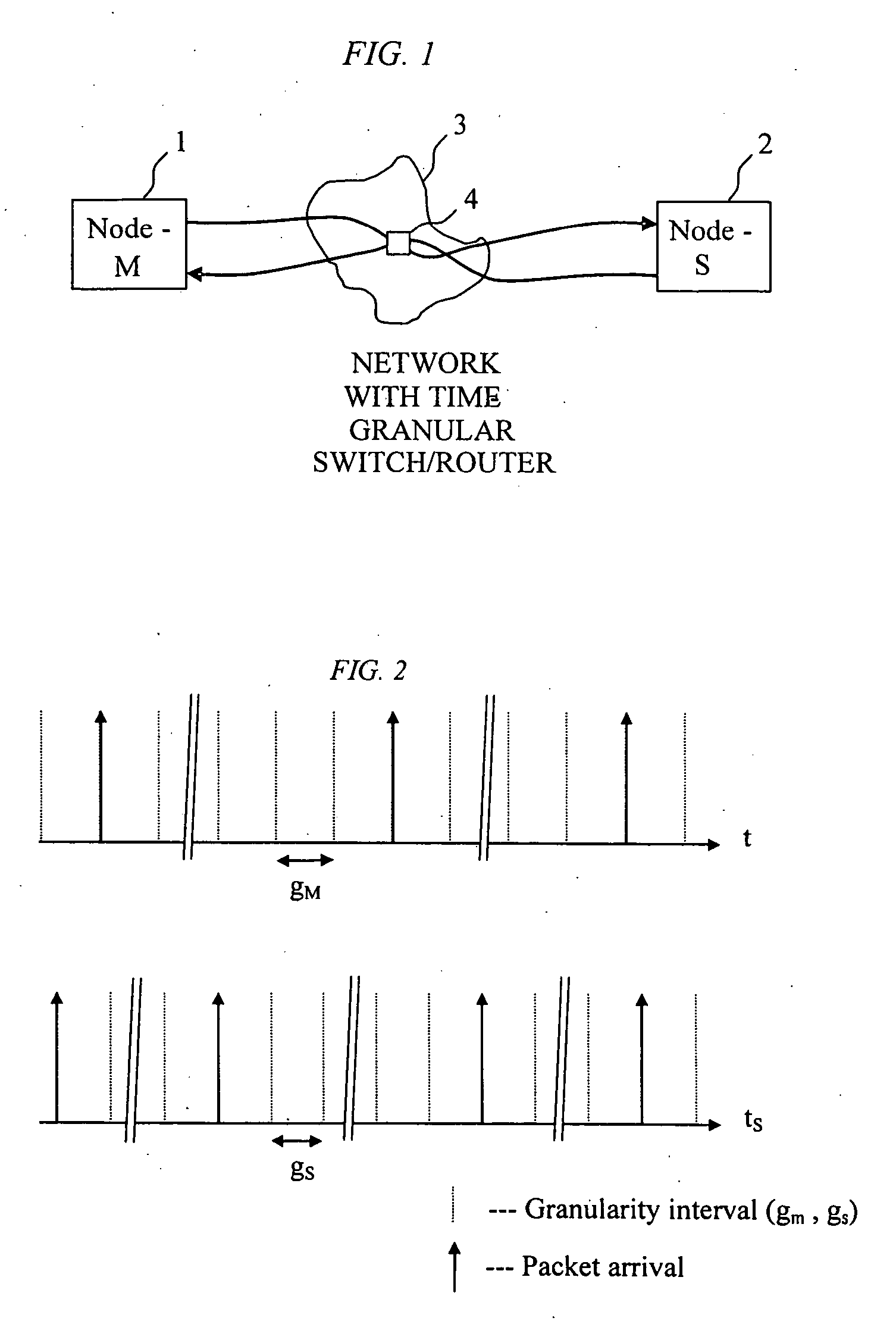
It is not possible to determine the transit time to a degree of precision better than the underlying timing granularity, and so the granularity of the network results in a loss of precision in the timing information exchanged between the source and destination nodes.

Method used


Image

  • Method of recovering timing over a granular packet network
  • Method of recovering timing over a granular packet network
  • Method of recovering timing over a granular packet network

Examples


Embodiment Construction

[0027] This invention describes a method for clock synchronization between master and slave nodes when packet delay variations are a cause of a time granular switching or routing component that schedule packets to their output on distinct multiples of an underlying time grid. The method described also applies when a series of such components are running at one common time grid such as in SDH and TDM networks.

[0028] A set of nodes is connected to a communication network. The network contains one switching / routing component that forwards these packets at distinct multiples of an underlying time grid. The network could also contain a series of these components that forward packets at a common time grid. Each node is provided with a local clock that is used to determine the arrival time of a packet from the network. Slave nodes send packets through the network to the master node. The master node sends the arrival time of the packet to the originating slave node. The slave note measures...


PUM


Abstract

A method is disclosed for recovering timing information between master and slave nodes interconnected over a packet network having an underlying time grid with a distinct granularity. A series timing packets are exchanged between said master and slave nodes to measure the time offset of the time grid relative to clocks at the master and slave clocks. This offset is then used to either adjust the local clock at the slave node, or generate the clock using a digital controlled oscillator.

Description

FIELD OF THE INVENTION [0001] This invention relates to the field of packet networks, and in particular to a method of recovering timing information over such networks. BACKGROUND OF THE INVENTION [0002] When time-sensitive data, such as voice or video data, is sent between a source node (Master) and destination node (Slave) over a packet network, the source and destination nodes will have local clocks that are not synchronized. Some method is needed for recovering the source clock at the destination node in order to recover the time-sensitive data. [0003] Existing time distribution systems, such as Network Time Protocol (NTP), IEEE-1588, that use packet networks to synchronize clocks send so-called timing packets in both directions between the source and destination nodes. From these packets the transmission time is compared with the arrival time to enable the precise packet transit time to be determined. The clock frequency of the destination node is adjusted to retain a measured ...

Claims


Application Information

Patent Timeline
Patent Type & Authority Applications(United States)
IPC IPC(8): H04L7/00H04J3/06
CPCH04J3/0667H04J3/0664H04L7/00
Inventor REPKO, WILLEM L.VAN DER VALK, ROBERTUS LAURENTIUS
Owner ZARLINK SEMICON LTD
Learn More