Bonding by induced high-rate of shear deformation
a bonding web and high-rate technology, applied in mechanical working/deformation, other domestic articles, chemistry apparatus and processes, etc., can solve the problems of non-adhesive bonding techniques having difficulty forming adequate bonding between materials, providing the desired combination of bonding speed and bonding strength between the target materials, etc., to achieve high bonding pressure value, low cost, and pattern surface speed
- Summary
- Abstract
- Description
- Claims
- Application Information
AI Technical Summary
Benefits of technology
Problems solved by technology
Method used
Image
Examples
example-1
[0121] In this example, the rotary pressure bonding system employed a FEMACCANICA pressure bonder which was obtained from Fameccanica.Data SpA, a business having offices located in San Giovanni Teatino (Abruzzi), ITALY. The employed web materials included a 0.5 osy (17 g / m2) spunbond-meltblown-spunbond (SMS) laminate, nonwoven fabric composite; a 0.55 osy (18.7 g / m2) spunbond (SB) nonwoven fabric; a 0.00075 inch (0.019 mm) thick printed polyethylene film (PE-p); and a 0.00075 inch (0.019 mm) thick, white (non-printed) polyethylene film (PE-w). Five target web combinations of the web materials were bonded. Bonding speeds varied from 200 feet per minute to 1000 ft / min (fpm) (1.02-5.08 m / sec), and nip forces ranged from 1,800 to 14,500 lb / in (0.32*106-2.6*106 N / m).
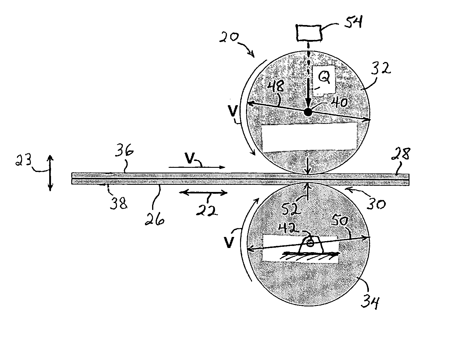
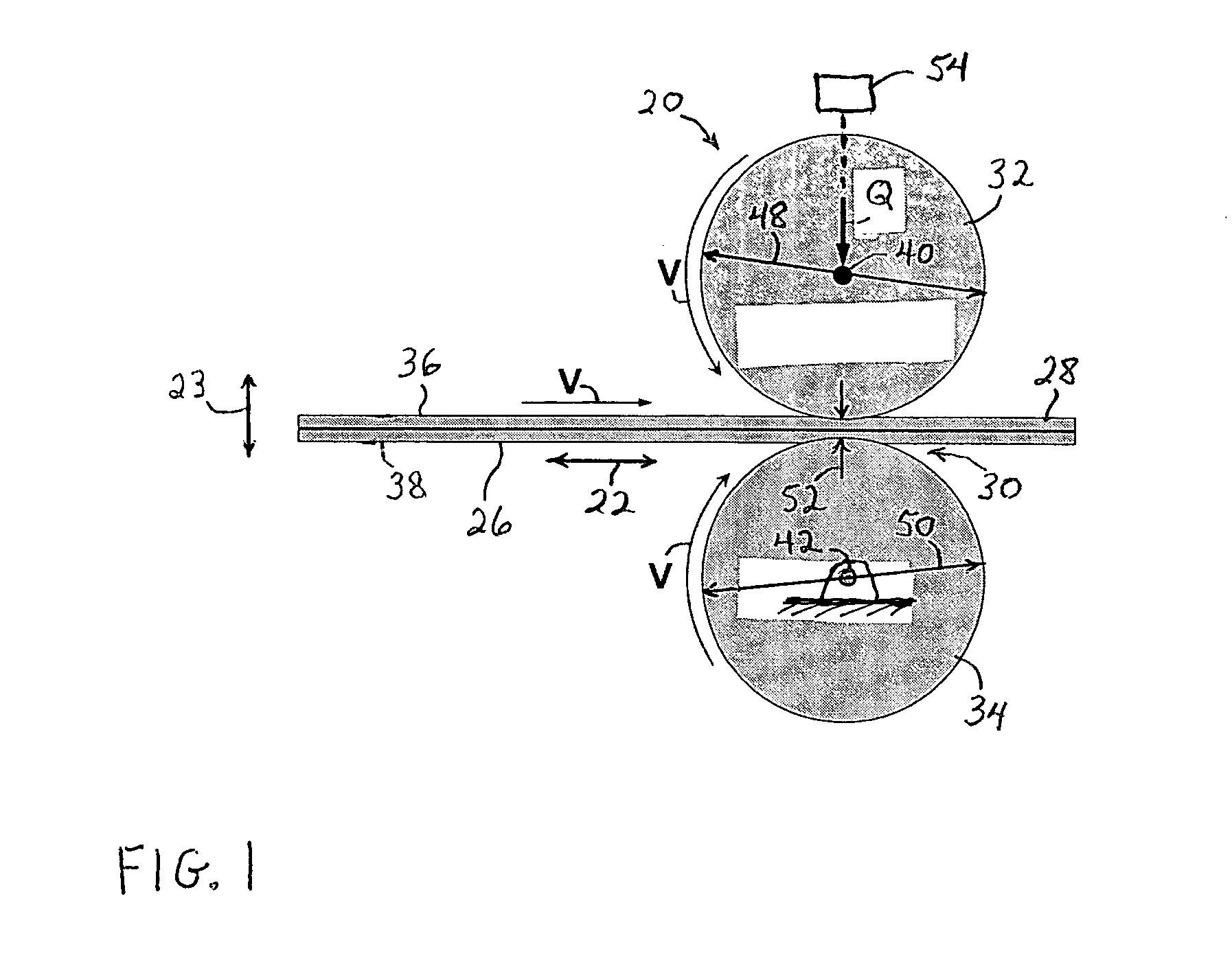
[0122] As illustrated in FIG. 1, the pressure bonding process and apparatus included a cooperating pair of bonding rollers provided by the representatively shown pattern roller 32 and an anvil roller 34. The anvil roller was...
example-2
[0136] Additional examples provided data pertaining to the process variables of bonder temperature, bonding speed and bonding pressure value in the nip region between the bonding rollers. The data also pertain to the influences that these variables can have on the bond strength between different combinations of target web materials.
[0137] It has been desirable to eliminate the pre-heating function from the bonding system. Accordingly, the influence of the bonder temperature on the results of the pressure bonding was investigated to more fully understand the fundamental mechanisms of non-adhesive, mechanical bonding. Rotary pressure bonding tests were conducted using a JOA pressure bonder, which was obtained from CURT G. JOA, Inc., a business having offices located in Sheboygan Falls, Wis., U.S.A. The employed pattern roller had the characteristics and parameters set forth in the following Table 4.
TABLE 4Parameters of JOA pressure bonder and pin pattern.BonderAir cylinderPin patte...
example-3
[0152] Further examples examined the effects of the pattern roller diameter on the rotary pressure bonding (RPB) method and apparatus of the invention. To evaluate the effects of roll diameter on RPB, two trials were carried out: the first trial was using a bonder with a 176 mm diameter pattern roll, Fameccanica pressure bonder (FAME), and a development pressure bonder (DPB) with a 304.47 mm diameter bonder. Neither the FAME nor the DPB employed an auxiliary heating unit. Details of the pressure bonders are set forth in the following Table 7.
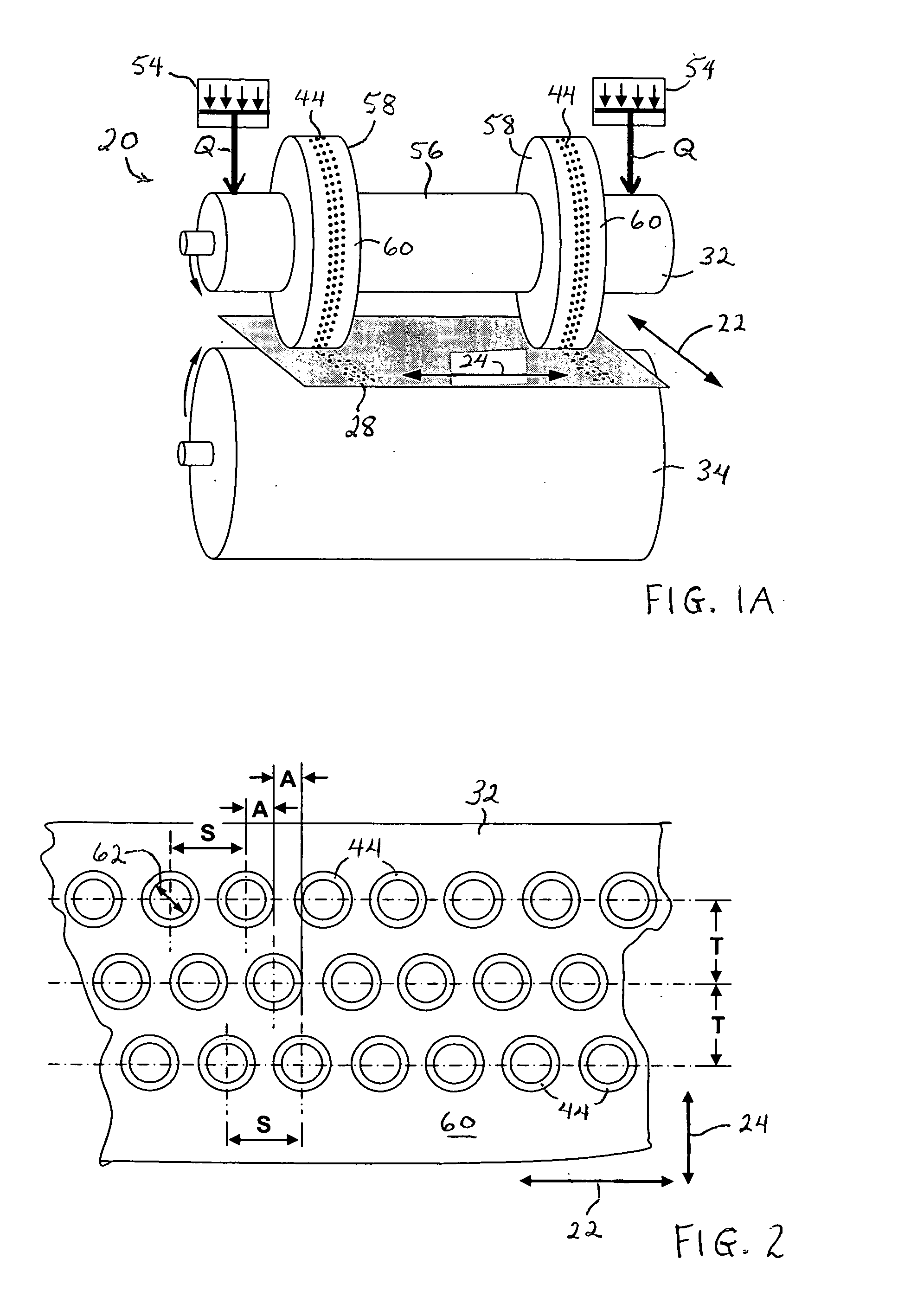
TABLE 7Parameters of pressure bonders and pin patternsBonderAir cylinderPin pattern (circular shape pin)D1D2D3D4HSTAmmmmmmNcNsNfNlmmmmmmmmmmDPB304.47304.47152.42423.5*0.910.791.591.330.45FAME1651761252123.5*0.910.791.591.330.45
*The number of pins in the fourth line is reduced to the half of the other lines by skipping a pin for every other pin; or in the other words, the pin interval in the fourth line is 2S, i.e., 3.18 mm.
D1 - anvil roller d...
PUM
| Property | Measurement | Unit |
|---|---|---|
| Temperature | aaaaa | aaaaa |
| Temperature | aaaaa | aaaaa |
| Fraction | aaaaa | aaaaa |
Abstract
Description
Claims
Application Information
 - R&D
- Intellectual Property
- Life Sciences
- Materials
- Tech Scout
- Unparalleled Data Quality
- Higher Quality Content
- 60% Fewer Hallucinations
Browse by: Latest US Patents, China's latest patents, Technical Efficacy Thesaurus, Application Domain, Technology Topic, Popular Technical Reports.
© 2025 PatSnap. All rights reserved.Legal|Privacy policy|Modern Slavery Act Transparency Statement|Sitemap|About US| Contact US: help@patsnap.com


