Open type water storage water heater
A water heater and open-type technology, applied in the field of open-type storage water heaters, can solve the problems that open-type water heaters cannot achieve central water supply, low reliability, and high cost, and achieve the effects of simple structure, extended service life, and low pressure bearing value.
- Summary
- Abstract
- Description
- Claims
- Application Information
AI Technical Summary
Problems solved by technology
Method used
Image
Examples
Embodiment 1
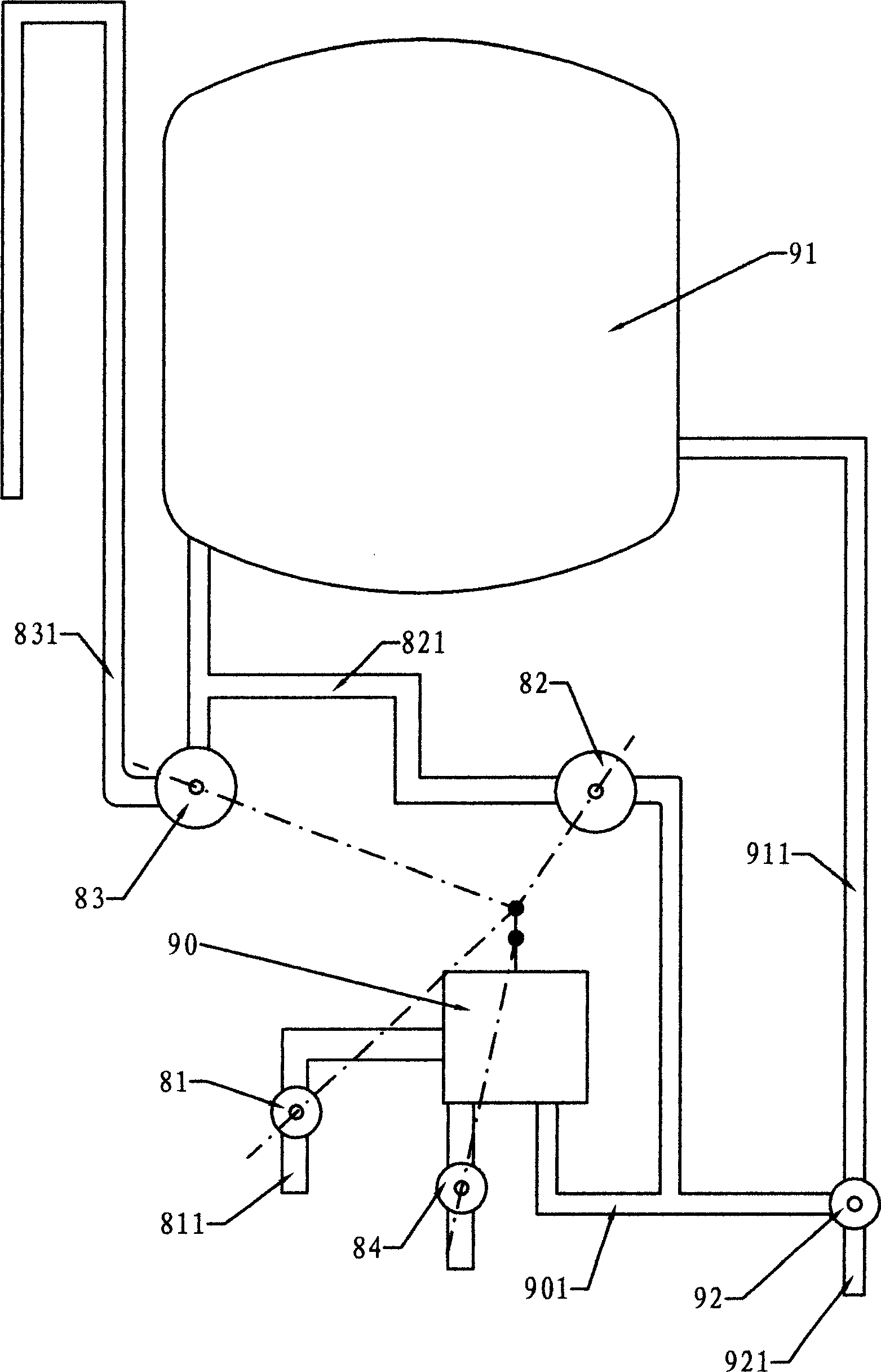
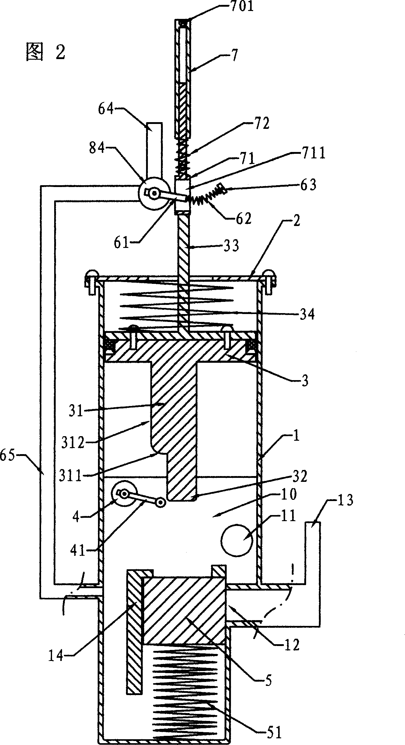
[0038] Embodiment one, see figure 1 , the open storage water heater includes a water tank 91, a heating element (not shown in the figure), a hot water pipe 911, a water mixing valve 92, an overflow pipe 831, a running water pipe 811 and a water supply pipe 821, and a water mixing valve 92 The hot water inlet is connected to the hot water pipe 911 and the cold water inlet connection pipe 901, and the hot water valve arranged between the hot water pipe 911 and the water outlet pipe 921 in the mixing valve 92 is used as a control valve, and the connection between the pipe 901 and the tap water pipe 811 The indirect water control expansion device 90 and the water inlet valve 81 are connected to the normally closed water supply valve 82 between the connecting pipe 901 and the water supply pipe 821; the normally open overflow valve 83 is connected between the water supply pipe 821 and the overflow pipe 831; the water control expansion device 90 and the The dotted line between the ov...
Embodiment 2
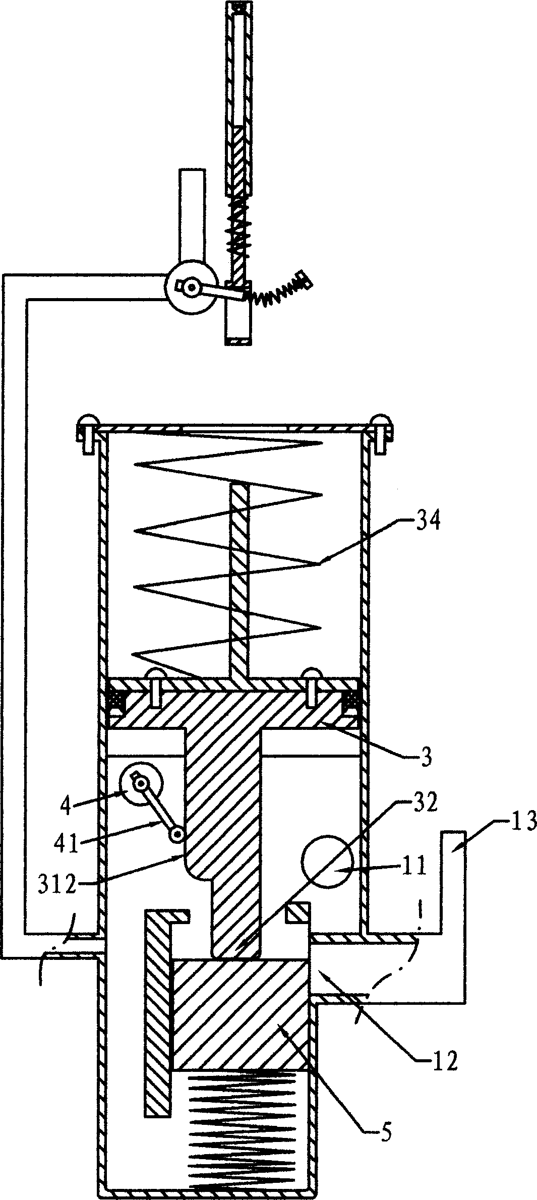
[0042] Embodiment 2. Figure 6 is a schematic diagram of the connection structure and control principle of this embodiment. The difference between Embodiment 2 and Embodiment 1 is that the water mixing valve in Embodiment 1 is changed to a faucet-type water outlet valve 920. Between the water outlet valve 920 and the hot water pipe 99, the one-way valve 910 is used as the control valve, and the joint 9011 between the connecting pipe and the water outlet valve is replaced with a smaller pipe diameter. figure 1 The same, and adopt the water control expansion device with the structure shown in Figure 2, the structure of the stator and moving plate in the switching valve also adopts Figure 4 and Figure 4 respectively Figure 5 The reason why the connection part 9011 adopts a smaller pipe diameter here is to prevent all the water in the pipe from flowing away through the water outlet valve after the water outlet valve 920 is opened, and the hot water in the water tank cannot be eject...
Embodiment 3
[0043] Embodiment three, see Figure 7 , the difference between the third embodiment and the second embodiment is only that the one-way valve in Figure 6 is changed to Figure 7 The normally closed cut-off valve 9100 is used as the control valve, and the stop valve 9100 is controlled by the expansion wall in the water-controlled expansion device. Similarly, the stop valve 9100 can also be integrated in the switching valve together with the overflow valve and the water supply valve. Its working principle is similar to that of the above-mentioned embodiment, and will not be described here.
PUM
 Abstract
Description
Claims
Application Information
 - R&D
- Intellectual Property
- Life Sciences
- Materials
- Tech Scout
- Unparalleled Data Quality
- Higher Quality Content
- 60% Fewer Hallucinations
Browse by: Latest US Patents, China's latest patents, Technical Efficacy Thesaurus, Application Domain, Technology Topic, Popular Technical Reports.
© 2025 PatSnap. All rights reserved.Legal|Privacy policy|Modern Slavery Act Transparency Statement|Sitemap|About US| Contact US: help@patsnap.com


