Water control apparatus for water storage type water heater
A water control device and water heater technology, applied in water heaters, fluid heaters, lighting and heating equipment, etc., can solve the problems of short life, poor safety, and high water tank costs
- Summary
- Abstract
- Description
- Claims
- Application Information
AI Technical Summary
Problems solved by technology
Method used
Image
Examples
Embodiment 1
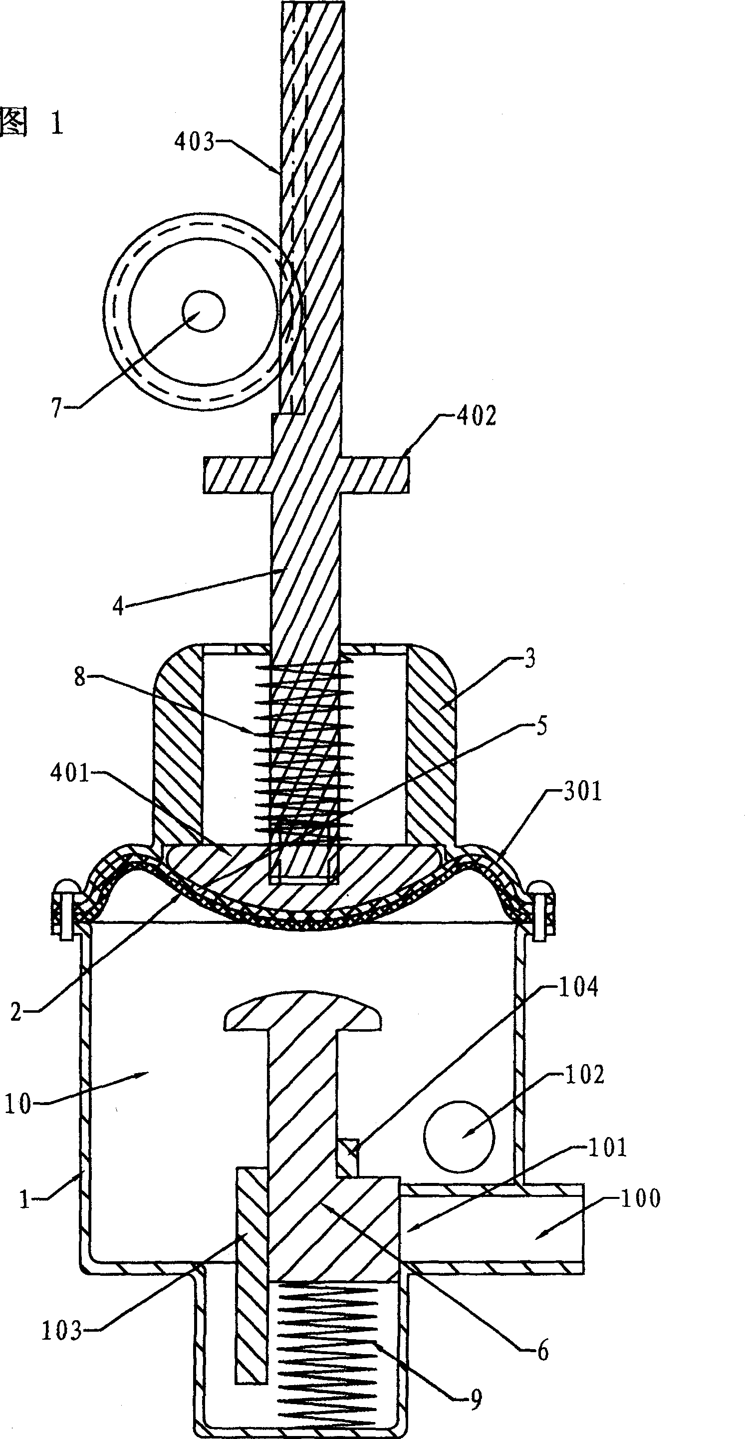
[0031]Embodiment 1, see Fig. 1, the water control device of the storage type water heater is in a standby state, it includes a connecting bracket 3, a valve body 1, a switch valve 7 and an adhesive film 2 used as an expansion wall, and the inner chamber of the valve body 1 There is an adhesive film 2 and a fiber cloth 5 sandwiched between the opening and the connecting bracket 3, and the valve body 1 and the adhesive film 2 form an expansion chamber 10; a head 401 is arranged on the outside of the fiber cloth 5, and the side of the head 401 facing the fiber cloth is On the arc surface, the head 401 is fixed on the control rod 4 that controls the switching valve 7. A spring 8 is arranged between the control rod 4 and the connecting bracket 3. The elastic force of the spring 8 is transmitted to the rubber through the head 401 of the control rod and the fiber cloth 5. The membrane 2, that is, the control rod 4 is installed between the spring 8 and the film 2, so when the film 2 mo...
Embodiment 2
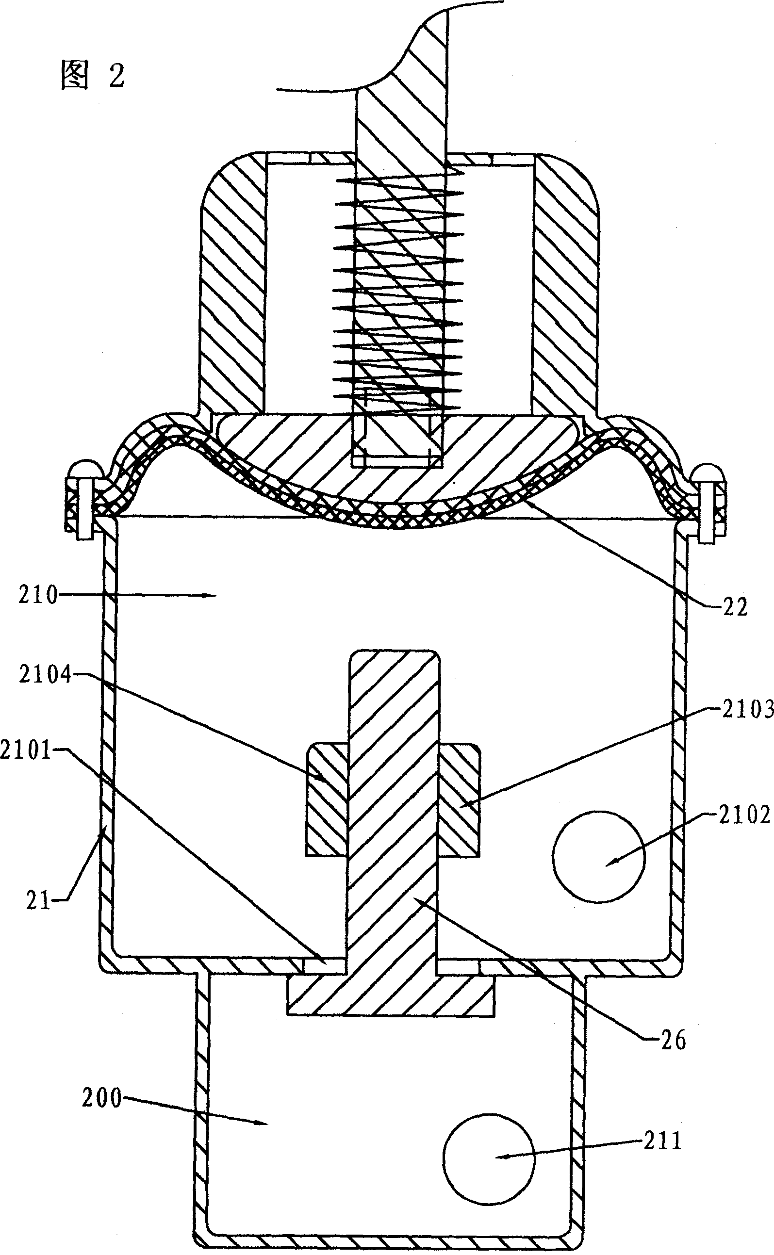
[0035] Embodiment 2, FIG. 2 is a schematic diagram of the internal structure of Embodiment 2 of the water control device for a storage-type water heater according to the present invention; it differs from Embodiment 1 only in the relative positions of the water blocking block 26 and the valve hole 2101, The water inlet 211 is connected to the water pipe so that the water inlet chamber 200 communicates with the water pipe. A valve hole 2101 is provided between the water inlet chamber 200 and the expansion chamber 210, and the axial section is " The upper part of the "shaped self-closing water blocking block 26 passes through the valve hole 2101 and extends between the guide blocks 2103 and 2104 in the valve body 21. The water blocking block 26 makes its crown block the valve hole 2101 by its own buoyancy, and the water blocking When the block 26 is close to the valve hole 2101, there is a drainage gap between the two, and the valve body 21 is also provided with a water outlet h...
Embodiment 4
[0037] Embodiment four, Figure 10 It is a schematic diagram of the internal structure of Embodiment 4 of the water control device for the storage-type water heater of the present invention. from Figure 10 It can be seen that the piston 62 as the expansion wall and the valve body 61 enclose an expansion chamber 610, the valve body is provided with a water inlet chamber 600 and a water outlet hole 6102, and a spring 63 is arranged between the piston and the connecting bracket 64, which is fixed on the piston The control rod 620 of the switch valve is engaged with the switch rod of the switch valve 67. The switch rod of the switch valve is located in the valve body 61. There is a valve hole 6101 between the water inlet chamber and the expansion chamber. The control rod is also provided with a guide rod 651 and a limit The position block 621 is used to guide and limit the water blocking block 65 sleeved outside the guide rod. A return spring 652 is arranged between the control ...
PUM
 Abstract
Description
Claims
Application Information
 - R&D
- Intellectual Property
- Life Sciences
- Materials
- Tech Scout
- Unparalleled Data Quality
- Higher Quality Content
- 60% Fewer Hallucinations
Browse by: Latest US Patents, China's latest patents, Technical Efficacy Thesaurus, Application Domain, Technology Topic, Popular Technical Reports.
© 2025 PatSnap. All rights reserved.Legal|Privacy policy|Modern Slavery Act Transparency Statement|Sitemap|About US| Contact US: help@patsnap.com


