
Method for operating a PMC memory cell and CBRAM memory circuit

a technology of memory cell and circuit, applied in the field of operation of pmc memory cell and cbram memory circuit, can solve problems such as worsening, and achieve the effect of stabilizing the programmed state of the pmc memory cell, selectively developing and diminishing the conductive path

Active Publication Date: 2006-11-23
ADESTO TECH +1
View PDF5 Cites 41 Cited by
  • Summary
  • Abstract
  • Description
  • Claims
  • Application Information

AI Technical Summary

Benefits of technology

[0009] One aspect of the present invention provides a method for operating a PMC memory cell by which the data retention in the PMC memory cell is enhanced. Furthermore, another aspect of the present invention provides that the method for operating the PMC memory avoids an imprinted programmed state in the PMC memory cell.
[0010] A further aspect of the present invention provides a CBRAM memory circuit having a CBRAM memory array including at least one PMC memory cell wherein the data retention in the PMC memory cell is enhanced.
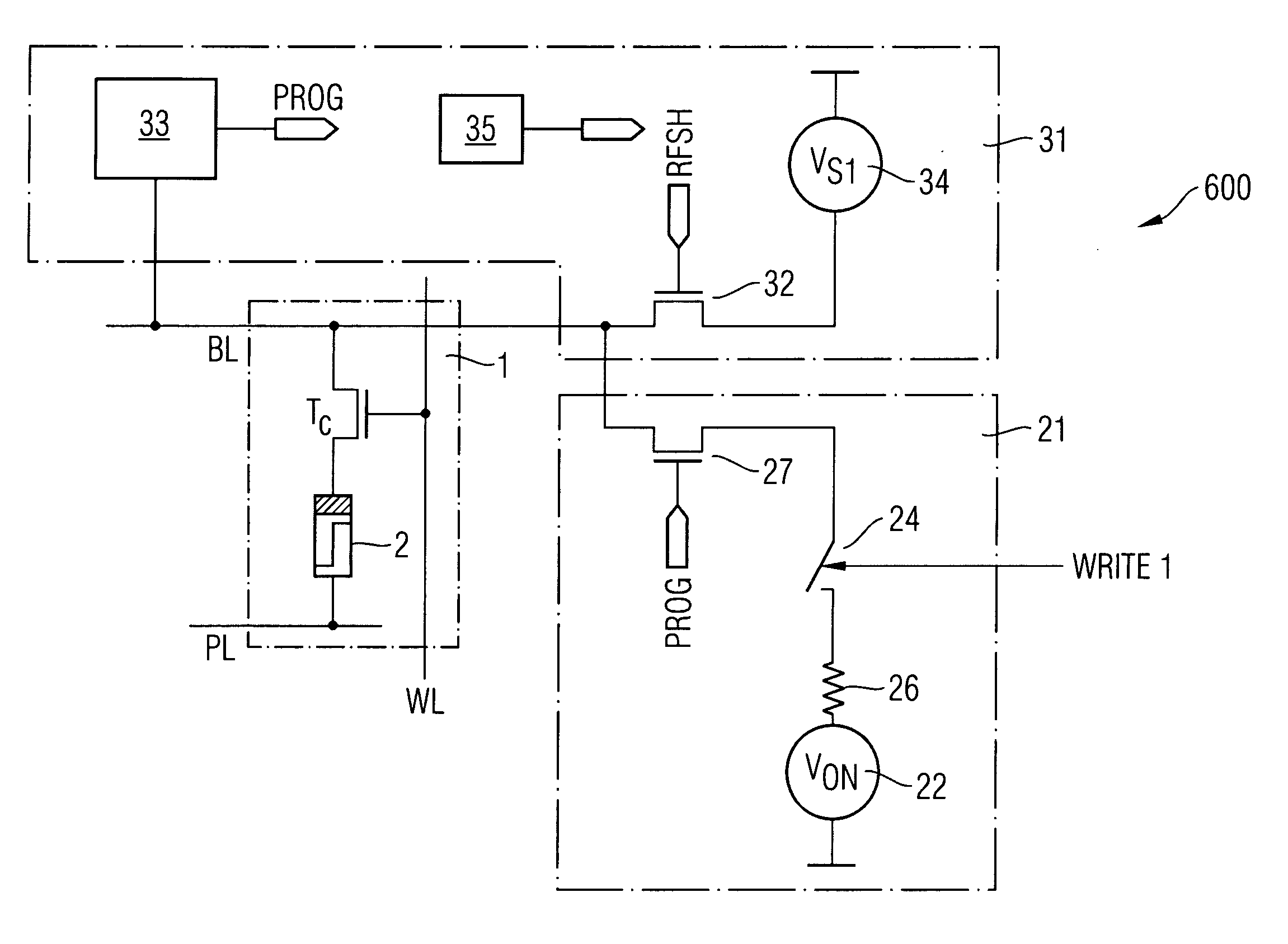
[0011] One embodiment of the present invention relates to a method for operating a PMC memory cell for use in a CBRAM memory array, wherein the PMC memory cell includes a solid electrolyte which is adapted to selectively develop and diminish a conductive path depending on an applied electrical field. The PMC memory cell is programmed to change to a programmed state by applying a programming voltage, and the PMC memory cell is erased to change to an erased state by applying an erase voltage. A refresh voltage is applied to the PMC memory cell at a predetermined time to stabilize the programmed state of the PMC memory cell, wherein the refresh voltage is selected such as that, while applying the refresh voltage, a programming of the PMC memory cell in the erased state to a programmed state is prevented, and that by applying the refresh voltage a stabilizing of the programmed state of the PMC memory cell is performed.

Problems solved by technology

This effect depends on the start resistance and becomes even worse at higher temperatures.
Another issue while storing data in the PMC memory cell lies in that an “imprinting” of data occurs if the programming voltage is applied for a successive number of times when the programmed state is to be written into a PMC memory element.

Method used


Image

  • Method for operating a PMC memory cell and CBRAM memory circuit
  • Method for operating a PMC memory cell and CBRAM memory circuit
  • Method for operating a PMC memory cell and CBRAM memory circuit

Examples


Embodiment Construction

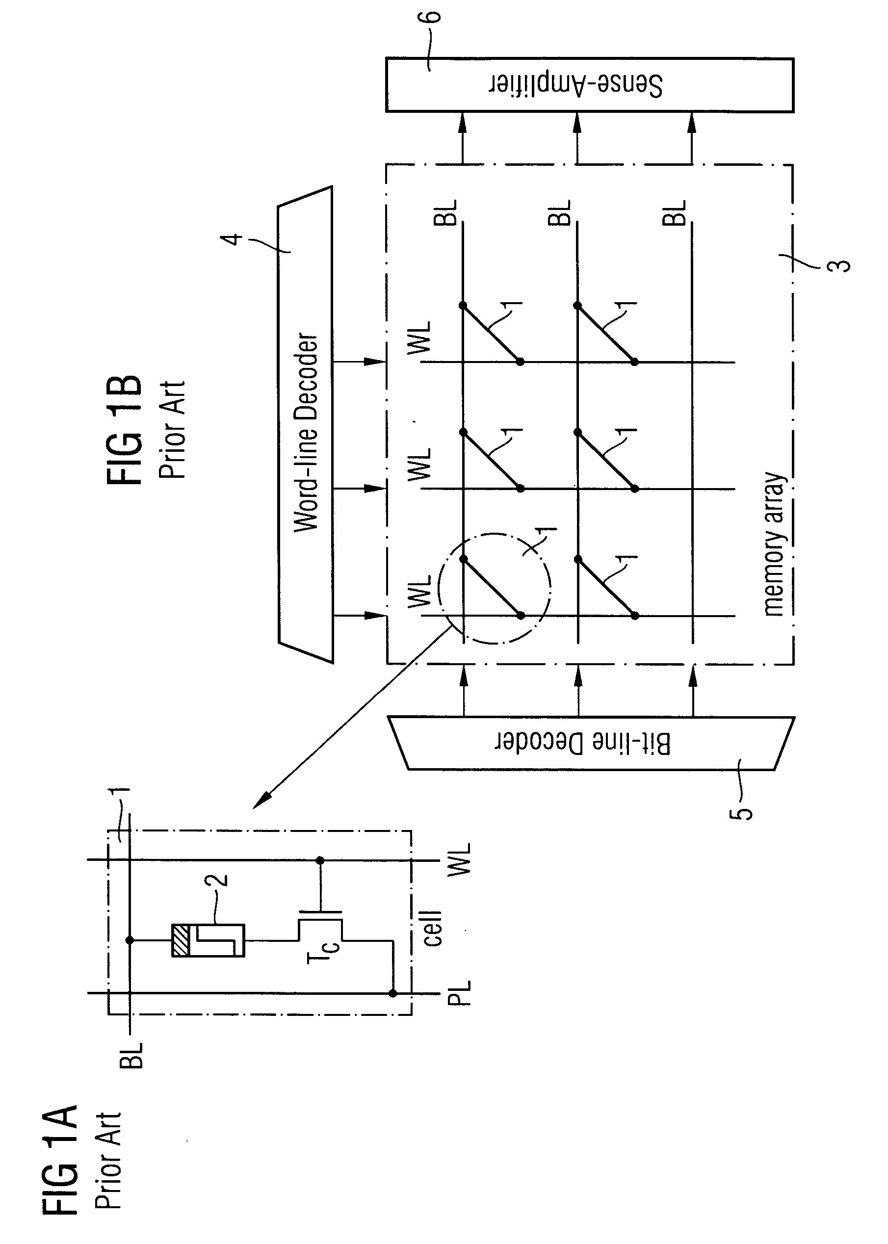
[0031] In FIG. 1A, an example of a PMC memory cell 1 according to the prior art is depicted. The PMC memory cell 1 is a part of a CBRAM memory array 3 including word lines WL, bit lines BL and plate lines PL. The plate line PL is usually set to a predetermined potential known as the plate line voltage. The word line WL is connected to a gate of a cell transistor TC which is connected in series to a PMC memory element 2. Depending on an activation signal on the word line, a voltage may be applied to a PMC memory element 2, connected between the bit line BL and the plate line PL via an activated cell transistor TC, for writing a state and reading out the stored state into / of the PMC memory cell 1.

[0032] In FIG. 1B, a CBRAM memory array 3 is depicted including a plurality of PMC memory cells 1 as shown in FIG. 1A arranged on word lines WL and bit lines BL. The PMC memory cells 1 are indicated as thicker black line segments between the word lines and bit lines BL for ease of illustrati...


PUM


Abstract

The present invention relates to a method for operating a PMC memory cell for use in a CBRAM memory array, wherein the PMC memory cell includes a solid electrolyte which is adapted to selectively develop and diminish a conductive path depending on an applied electrical field. The PMC memory cell is programmed to change to a programmed state by applying a programming voltage, and the PMC memory cell is erased to change to an erased state by applying an erase voltage. A refresh voltage is applied to the PMC memory cell at a predetermined time to stabilize the programmed state of the PMC memory cell, wherein the refresh voltage is selected such as that, while applying the refresh voltage, a programming of the PMC memory cell in the erased state to a programmed state is prevented, and that, by applying the refresh voltage, a stabilizing of the programmed state of the PMC memory cell is performed.

Description

BACKGROUND OF THE INVENTION [0001] 1. Field of the Invention [0002] The present invention relates to a method for operating a PMC memory cell, particularly for use in a CBRAM memory array. The present invention further relates to a CBRAM memory circuit including a CBRAM memory array having at least one PMC memory cell. [0003] 2. Description of the Related Art [0004] Memory cells comprising a solid electrolyte material are well known as PMC (programmable metallization cell) memory cells. Memory devices including such PMC memory cells are known as CBRAM (conductive-bridging random access memory) devices. The storing of different states in a PMC memory cell is based on the developing or diminishing of a conductive path in the electrolyte material between electrodes based on an applied electrical field. Although the electrolyte material has a high resistance, the conductive path between electrodes has a low resistance. Thereby, the PMC memory cell can be set to different states dependin...

Claims


Application Information

Patent Timeline
Patent Type & Authority Applications(United States)
IPC IPC(8): G06F13/28
CPCG11C13/0011G11C13/0033G11C2213/79G11C16/3431G11C2013/009G11C13/0069G11C13/0064
Inventor SYMANCZYK, RALFLIAW, CORVIN
Owner ADESTO TECH
Learn More